View Tunnel Designs
Use the Tunnel View command to view and edit the properties and changes in the cross-sectional shape of a tunnel design along its entire length. You can also display cross-sections from an associated corridor template in the view so you can check how the tunnel shape corresponds to the road's shape.
Note: If you have created a designed tunnel mesh for a tunnel, you can view the shape of a tunnel design in the 3D View, where you can view the tunnel from various perspectives. You can also use the Walk-Through Viewand 3D Drive Viewto further explore the interior and exterior of the tunnel.
Prerequisites:
Licensed module. See the Subscription Plans page. For a license matrix by command, see the License page in the TBC Community. Also see View and manage licensed features.
To view a tunnel:
- Select Tunnel View in Tunnels > View to display the Tunnel View tab.
- In the Tunnel drop-down list located in the lower-left corner of the tab, select the tunnel you want to view.
- To display cross-sections from a related road corridor template, click theView button located in the lower-right corner of the tab. Then, in the View Roads and Tunnels dialog, check the box for each corridor to display, and click OK.
Only corridors that have the same horizontal and vertical alignment as the selected tunnel corridor are listed. All material layers in the selected corridors will be displayed
- To display multiple tunnels at the same time, click theView button located in the lower-right corner of the tab. Then, in the View Roads and Tunnels dialog, check the box for each additional tunnel you want to display, and click OK.
Only tunnels that have the same horizontal and vertical alignment as the selected tunnel corridor are listed. All material layers in the selected corridors will be displayed.
- To configure the Tunnel View, click the Project Settings button located in the lower-right corner of the tab. See Project Settings > View Settings > Tunnel View for more information.
- Use the slider control located at the bottom of the tab to "move" through the tunnel along the alignment to view the various tunnel and (optionally) corridor shapes and interpolations between those shapes.
In addition to the movable slider control button located directly on the control bar, the first two arrow buttons located on the right side of the bar allow you to move the slider to the next or previous station in increments specified in the tunnel's properties. (Right-click the tunnel in the Project Explorer and select Properties to change). The second two buttons allow you to move the slider to the next or previous station to which a new tunnel template has been applied or a horizontal or vertical alignment point is located.
Shape specifications, including interpolated values between shapes, are displayed in the lower portion of the tab, based on the currently selected station.
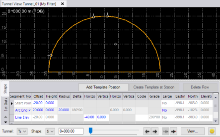
Following is an example of the Tunnel View with a horizontal tunnel.
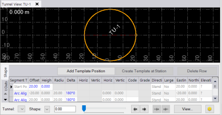
This next example shows the Tunnel View with a vertical shaft tunnel.
- Select any of the sub-tabs located on the lower-left side of the Tunnel View tab to view and edit Shape, Set Outs, Rotation, and Offset properties.
- If you are viewing the tunnel at a station at which a
 non-interpolated tunnel shape has been applied, you can edit the tunnel shape directly on the Shape sub-tab. For additional instructions, see Edit a Tunnel Shape
 - If you are viewing the tunnel at a station at which an interpolated tunnel shape has been applied, you can select the tunnel template position in the lower portion of the tab and then right-click to display a pop-up menu that allows you to create a new tunnel shape template from the interpolated shape. For more information, see Create a Tunnel Shape Template from Interpolated Shapes.
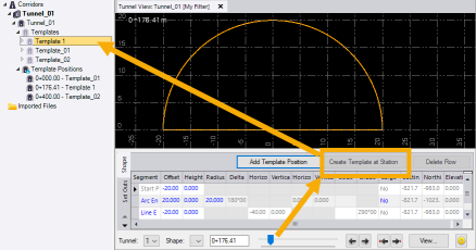
- If you are viewing the tunnel at a station at which a
