Assign Tunnel As-Built Points
Use the Assign Tunnel As-Built Points command to assign imported as-built points to stations in a tunnel design to compute overbreak and underbreak data displayed in the Tunnel View, a customizable tunneling report, and cross-section drafting sheet sets. As-built points can be used to create an as-built tunnel mesh for additional tunnel inspection.
Prerequisites:
- Licensed module. See the Subscription Plans page. For a license matrix by command, see the License page in the TBC Community. Also see View and manage licensed features.
To assign tunnel as-built points
- Select Assign Tunnel As-Built Points in Tunnels > Reports to display the Assign Tunnel As-Built Points command pane.
- Select the Tunnel to which you want to assign points.
- Select the Selection Method you want to use to assign points to the selected tunnel:
- From job file - This option enables you to assign to the tunnel all points contained in all imported job files in the project that were measured and assigned to a tunnel shape and station in Trimble Access.
- Optionally, check the Include disabled points check box and/or the Include backsight points check box.
- Click the Add button to see a list of the tunnel stations and the points to be assigned to each in the As-Built Points table located at the bottom of the command pane.
Optionally, you can right-click any row in the As-Built Points table and select to delete from the report the selected station and associated points or all stations and associated points.
- From point cloud - This option enables you to extract scan points from a point cloud and assign them to the tunnel at specified stations, which converts the points used in the As-Built Tunnel Report into points with IDs, optional layers, and/or feature codes.
Note: If the tunnel cloud is divided into multiple regions, you can assign points from different point cloud regions to them.
- In the Begin station and End station fields, enter the first and last in the range of stations to which you want to assign points from the point cloud. Alternately, pick the starting and ending stations along the alignment in the Plan View or 3D View.
- In the Station interval field, enter the distance between stations at which you want to assign scan points. Alternately, pick two points along the alignment in the Plan View or 3D View to specify the interval.
- Optionally, check the Include horizontal alignment stations, Include Vertical Stations, and/or Include template stations boxes to also assign scan points at important HAL points, VAL points, and tunnel template locations.
- Select the Tunnel shape to which you want to assign the points.
- Select one or more pre-defined Point cloud regions from which to extract the points to assign.
- In the Search distance field, enter the distance on either side of each station from which scan points will be collected.
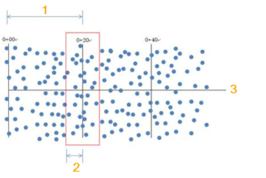
In the following example, 1 = station interval, 2 = search distance, and 3 = alignment.
- In the Shape sampling interval field, specify the distance around the selected tunnel shape at which to use the point cloud data.
The shape sampling interval is used to find the nearest point in the point cloud to each interval point on the tunnel shape. For the last point found, if the distance from the previous point is more than half of the interval, the point closest to the shape end point is assigned.
In the following example, the shape sampling interval is 1 m.
1 = shape start point, 2 = shape end point, 3 = target point on shape, 4 = scan point, 5 = sampled scan point.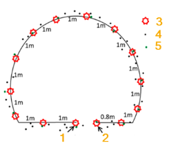
- To use Automatic point numbering for point IDs, enter a Starting point value. The {station} and {index} values are replaced with a numeric value that is automatically incremented. You can omit {station}, but not {index}. If a point with the same is already exist, the name of the new point will be appended with a suffix like _ 02.
- Points layer - Select the layer on which you want the newly created points to reside.
- Feature code - If you need to use the points in feature code processing, enter a code in the Feature Code field.
- Click Add to create points from the point clouds at the specified interval and using the shape sampling interval. The points are named, layered, and feature coded as specified. Click Remove to clear previously assigned points from the point cloud.
- Specific station - This option enables you to specify the points you want to assign to the tunnel for a specified tunnel shape at a specified station.
- Click in the Station field and then enter or select the station to which you want to assign points.
- Select the Tunnel shape to which you want to assign points.
- Click in the Points field and then enter or select the points you want to assign.
- Optionally, check the Include disabled points check box and/or the Include backsight points check box.
- Click the Add button to see a list of the tunnel stations and the points to be assigned to each in the As-Built Points table located at the bottom of he command pane.
Optionally, you can right-click any row in the As-Built Points table and select to delete from the report the selected station and associated points or all stations and associated points.
- Station interval - This option enables you to specify the points you want to assign to the tunnel for a specified tunnel shape at stations within a specified range at specified intervals.
- Click in the Begin Station field and then enter or select the first station in the range of stations to which you want to assign the points.
- Click in the End station field and then enter or select the last station in the range.
- Click in the Station interval field and then enter or select the station interval at which you want to assign points.
- In the Search distance field, enter the distance on either side of each station from which scan points will be assigned to the station.
In the following example, 1 = station interval, 2 = search distance, and 3 = alignment.
- Optionally, check the appropriate check box to Include horizontal alignment stations, Include Vertical Stations, and/or Include template stations to which you want to assign points.
- Select the Tunnel shape to which you want to assign points.
- Click in the Points field and then enter or select the points you want to assign.
- Optionally, check the Include disabled points check box and/or the Include backsight points check box.
- Click the Add button to see a list of the tunnel stations and the points to be assigned to each in the As-Built Points table located at the bottom of the command pane.
Optionally, you can right-click any row in the As-Built Points table and select to delete from the report the selected station and associated points or all stations and associated points.
When you run a report with as-built data, a multi-segment line is drawn connecting all of the as-built points. The line can then be compared with the tunnel shape to calculate overbreak and underbreak areas and volumes. The Closed tunnel as-built check box allows you to specify whether this line can straddle (cross) the starting point for the tunnel shape to connect as-built points on either side of it.
- From job file - This option enables you to assign to the tunnel all points contained in all imported job files in the project that were measured and assigned to a tunnel shape and station in Trimble Access.
- Do either of the following:
- Check the Closed tunnel as-built check box to specify that the line that is automatically drawn connecting all of the as-built points be allowed to straddle (cross) the starting point for the tunnel shape, resulting in a closed as-built line.
- Uncheck the Closed tunnel as-built check box to specify that the line that is automatically drawn connecting all of the as-built points not be allowed to straddle (cross) the starting point for the tunnel shape.
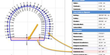
The following example shows the Tunnel As-Built Report with the Closed tunnel as-built check box checked. In this case, the as-built line crosses the tunnel shape's starting point (indicated by the large arrow), resulting in a closed as-built line. In this example, the overbreak area (indicated by the blue points and added blue highlighting) and underbreak area (indicated by the red points and added red highlighting) was computed and displayed based on the newly created as-built line in relation to the tunnel shape design.
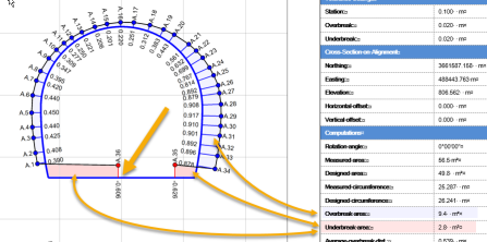
This next example shows the Tunnel As-Built Report with the Closed tunnel as-built check box unchecked. In this case, the as-built line does not cross the tunnel shape starting point (indicated by the large arrow), resulting in points A35 and A36 not being connected. Compare the underbreak area in this example with the previous example.
- If you want to assign additional points to this or another tunnel in the project, click the Apply button to assign the points currently displayed in the As-Built Points table and keep the command pane open. Otherwise, click the OK button to assign the selected points and close the command pane.
You are now ready to view the as-built points in the Tunnel View, run tunnel as-built reports and ASCII tunnel reports, and create tunnel cross-section drafting sheet sets that include as-built data.
