Compare Tunnel Meshes Using the Tunnel Inspection View
Use the Tunnel Inspection View to view a tunnel inspection map that compares the shape of two tunnel meshes to identify differences between them. Depending on the tunnel inspection map you select, you can compare a designed tunnel mesh to an as-built tunnel mesh (for example, compare the design mesh to an as-built excavation mesh). Or, you can select to compare an as-built tunnel mesh to another as-built tunnel mesh (for example, compare an as-built excavation mesh to an as-built shotcrete mesh).
Deviations between the two meshes are displayed in several different formats as described below.
Prerequisites:
- See the Subscription Plans page. For a license matrix by command, see the License page in the TBC Community. Also see View and manage licensed features.
- A tunnel inspection map.
To compare tunnel meshes:
- Do either of the following to display the Tunnel Inspection View.
- Select Tunnel Inspection View in Tunnels > View.
- In the Project Explorer, right click the Tunnel Inspection Map node and select Tunnel Inspection View.
The Tunnel Inspection View includes a set of view controls and three view tabs.
Note: Optionally, you can drag-and-drop any of the tabs tabs to rearrange the views.
- Manage the tabs as follow:
- Tunnel Inspection View tab - Use the controls located on this tab to do any of the following:
- Select a different tunnel inspection map using the Inspection map drop-down list.
- Select the station displayed in the Cross-Section View and Delta View using the station field or the slide control. (Also, see "Inspection Plan View" below.)
- Select the view tabs you want to display by clicking the View button to open the Show/Hide Views dialog.
- Change the colors and distance increments used to indicate mesh deviations in the Inspection Plan View and Cross-Section View by clicking the Edit Color Mapping button to open the Edit Color Mapping dialog. The current color key is displayed in the Inspection Plan View. (See "Inspection Plan View" below.)
- Change any of a number of related tunnel inspection settings by clicking the Project Settings button to open the Project Settings dialog. See instructions in "To change Tunnel Inspection View settings" later in this topic.
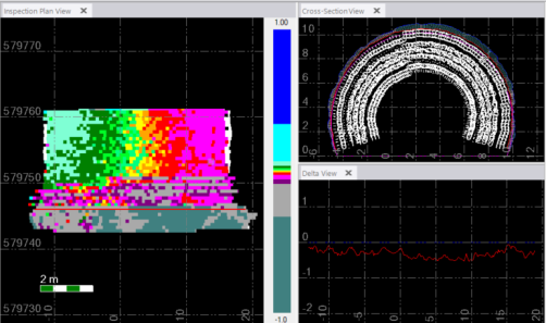
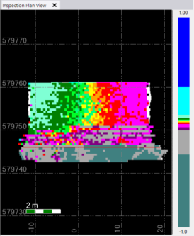
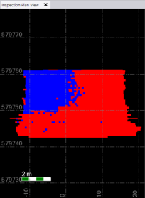
- Inspection Plan View - This view shows the base mesh "unfolded", flattened, and overlayed with a grid of custom-sized mesh cells whose colors indicate the distance between each base mesh cell and its corresponding comparison mesh cell. To flatten the base mesh to display its entire surface simultaneously in a planar view, the base mesh has been split along the tunnel alignment (dashed orange line below) and unfolded so that the center bottom area of the mesh is located on the outer edges of the image in the Inspection Plan View (as indicated by the arrows in the example below).
The color key on the right side of the tab indicates how the the colors are applied. Typical color usage is displayed in the Inspection Plan View example shown here.
In this example, dark blue (at the top of the scale) indicates that a comparison mesh cell is 1 m outside the corresponding base mesh cell (overbreak). Dark green (at the bottom of the scale) indicates that a comparison mesh cell is 1 m inside the corresponding base mesh cell (underbreak). The intervening colors indicate the overbreak and underbreak of the comparison mesh cell between -1.0m and 1.0 m.
This same color scheme is applied in the Cross-Section View to show overbreaks and underbreaks
Note: You can change the colors displayed in both of these views and the delta distances they represent, by clicking the Edit Color Mapping button on the Tunnel Inspection View tab. See Edit Color Mapping for a Surface or Difference Model for additional instructions.
Dark grey (not the medium grey used in the default color key as shown in the examples) indicates a mesh cell is beyond the tolerance specified in the Delta tolerance field in the Tunnel Inspection Map Properties pane and, as an outlier, is not providing a delta value. White indicates a mesh cell's delta value could not be computed (data missing).
The red horizontal line in the Inspection Plan View represents the location of the station currently selected.
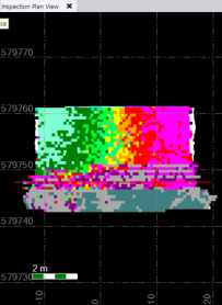
You can change the resolution (mesh cell size) displayed in the Inspection Plan View by clicking the the Project Settings button on the Tunnel Inspection View tab and editing the values in the the Linear direction resolution field and/or Linear cross-section resolution field in in Project Settings >Tunnel Inspection View. Note that changing to a higher resolution (smaller mesh cell size) can take a long time to process, depending on the size of the inspection map.
Optionally, you can change the Inspection Plan View and Cross-Section View to show only two colors (one for overbreaks and one for underbreaks) by clicking the Project Settings button on the Tunnel Inspection View tab and selecting Yes in the Show two colors only drop-down list in Project Settings >Tunnel Inspection View.
If your cursor is in the station edit field on the Tunnel Inspection View tab, you can specify the station to display in the other views by clicking directly on the Inspection Plan View.
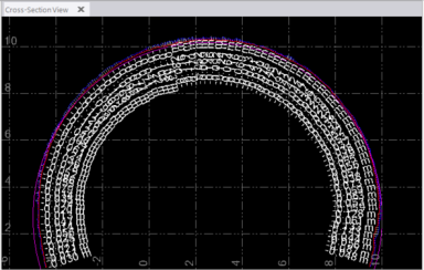
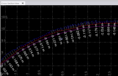
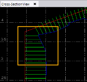
- Cross-Section View - View the deviation (represented by delta lines in the example below) between the base mesh (represented by the blue-lined shape in the example below) and comparison mesh (red-lined shape) at the specified station. The delta lines are color coded to indicate overbreaks and underbreaks.
Note the following:
- You can specify the color to be used for the base mesh and comparison mesh in Project Settings > Tunnel Inspection View > Cross-Section View.
- You can specify whether delta values are displayed, and if they are, whether they are fixed size or scaled in Project Settings > Tunnel Inspection View > Cross-Section View.
- You can specify whether or not to display a "tunnel shape" in the Cross-Section View (and specify its color) in Project Settings > View > Tunnel Inspection View > Cross-Section View. A "tunnel shape" is either (1) the shape of a design mesh used in the comparison either as the base mesh or the comparison mesh, or (2), if a design mesh is not used in the comparison, the shape of the base mesh.
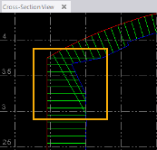
Because delta lines are drawn perpendicular to the base mesh, it is possible that they will overlap, as shown in the following example. Removing the longer delta lines that are crossing the shorter lines should give you more accurate results. To automatically remove the longer overlapping delta lines, select Yes in the Remove intersecting lines drop-down list in the Tunnel Inspection Map Properties pane. (The default setting is Yes.)
- Delta View - View the delta between the base mesh and comparison mesh at the specified station in a 2D graph. The base mesh line (blue in the example below) is always horizontal and flat. The comparison mesh delta line (red in the example) varies depending on the distance of delta from the base mesh across the tunnel's width.
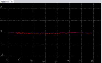
Note: You can specify the color to be used for the base line and deviation line in Project Settings > Tunnel Inspection View > Delta View.
- Tunnel Inspection View tab - Use the controls located on this tab to do any of the following:
- Use the various tabs in the Tunnel Inspection View to compare the two selected tunnel meshes.
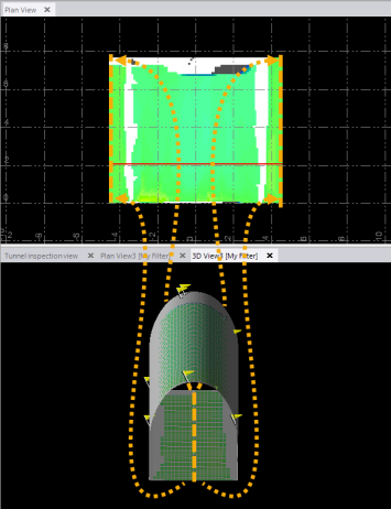
- To further compare the two tunnel meshes, ensure the selected tunnel inspection map is the only Tunnel Mesh selected in the View Filter Manager, and select 3D View in Views > 3D View or Plan View in Views > View.
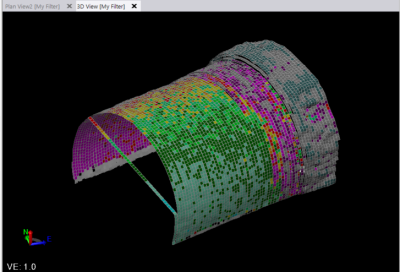
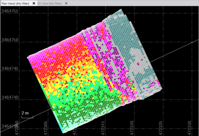
If an individual mesh cell or a group of contiguous mesh cells in the inspection map exceeds the Delta tolerance specified in the Tunnel Inspection Map Properties pane, an out-of-tolerance error flag is displayed in the graphic views. Also, if a delta cannot be computed, an error flag is displayed. Select Flags Pane in Views > View to see details about each displayed flag.
To change Tunnel Inspection View project settings:
There are a number of settings available in the Project Settings to specify how data is displayed in the Tunnel Inspection View, including color usage.
- Select Project Settings in the Quick Access Toolbar.
- In the Project Explorer, select View > Tunnel Inspection View.
- Change settings as necessary as described in View Settings.
