Create a Tunnel Shape
Use the Create Tunnel Shape command to define tunnel cross-section geometry that can be added to a tunnel template that, in turn, can be applied at any tunnel corridor station to define the shape of the tunnel at that station.
Note: If you already have a CAD drawing that defines the tunnel shape you want to create, import it into your project and see Create a Tunnel Shape from a CAD Object for instructions.
 To ensure smooth shape transitions through interpolation...
Prerequisites:
Licensed module. See the Subscription Plans page. For a license matrix by command, see the License page in the TBC Community. Also see View and manage licensed features.
To create a tunnel shape:
- If the Create Tunnel Shape command pane is not already displayed, select Create Tunnel Shape in Tunnels > Create to display it.
- Enter a Name for the new tunnel shape.
- Select the Tunnel and tunnel shape Template to which you want to add the new shape.
The new shape will be applied to the tunnel at one or more stations specified for the tunnel shape template.
- Optionally, to create the new tunnel shape based on an existing tunnel shape, do the following:
- In the Copy shape drop-down list, select the tunnel template: shape on which you want to base the new shape.
- Optionally, in the Concentric offset field, enter an offset value to create a concentric version of the source shape; that is, a shape that is either smaller or larger than the source shape based on a specified distance value, while maintaining the same aspect ratio.
The Concentric offset option allows you to, for example, easily create exterior and interior tunnel shapes.
Optionally, regardless of whether or not you used the Concentric offset option, you can edit the new copied shape as described in the rest of this topic.
- Click OK.
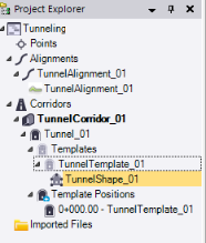
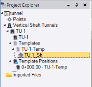
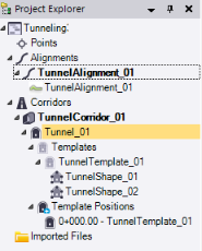
The new tunnel shape node displays in the Project Explorer, nested beneath the selected tunnel template node.
Following is an example showing a tunnel shape for a vertical shaft tunnel.
In addition, the Edit Tunnel Shape tab displays.
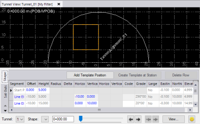
- In the tabular display located in the lower portion of the Edit Tunnel Shape tab, enter an alignment Offset and Height for the starting point for the tunnel shape, which you will "draw" by specifying additional instructions.
- In the second row in the table, select a Segment Type for the first segment to be drawn and then edit any of the editable (blue) values as necessary.
The editable values displayed depend on the Segment Type you select. For example, if you select Arc End Point and Radius, you can specify the Offset, Height, and Radius to define the end point for the new segment.
Note: To include Arc Direction properties in an exported tunnel design TXL file, be sure to use the latest version of the TXL exporter. The resulting TXL file cannot be imported into versions of TBC earlier than v5.80.
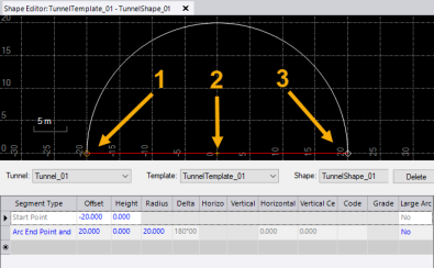
In the following example, the start point (1) was specified to be offset 20 m to the left of the alignment centerline (2) with no height change. The first segment was drawn using the Arc End Point and Radius option with a specified 20 m radius to a point that is offset 20 m to the right of the alignment with no height change (3).
Note: If your tunnel shape includes arc segments, it is recommended that you "draw" the shape by adding segments in a clockwise (left to right) sequence to avoid unexpected results.
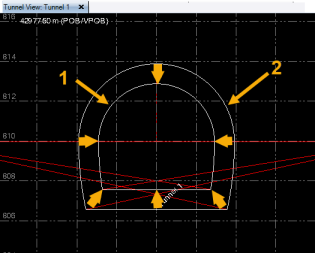
Following is an example of a vertical shaft tunnel shape.
- Add rows as necessary to define additional segments for the tunnel shape until all segments necessary to define the shape been created.
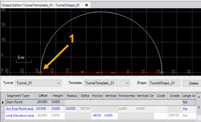
In the following example, a second segment has been drawn using the Line Elevation and Offset option with a specified horizontal distance of -40 m and no vertical distance change to connect back to the start point (1) and close the tunnel shape.
The new shape will be used to define the tunnel geometry at the station(s) at which its parent template is being applied.
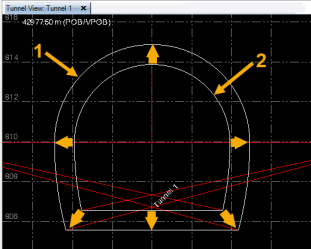
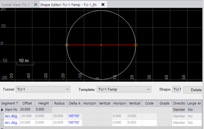
- If necessary, create additional tunnel shapes to include with the same tunnel template, resulting in multiple tunnel "layers." The following example shows two tunnel shapes linked to the same tunnel template as viewed in the Tunnel View.
If necessary, you can create shapes for other shape templates to be applied to the tunnel. See "To ensure smooth shape transitions" above for important information and instructions.
You can now create a designed tunnel mesh and view the shape in the 3D View.