Create a Tunnel Alignment
Use the Create Tunnel Alignment command to build a horizontal alignment (HAL) for a tunnel by entering values from engineering designs to define horizontal segments or curves at Points of Intersection (PIs). If needed, you can then define station equations and/or create a vertical alignment (VAL) using Vertical Points of Intersection (PVIs). For each HAL, you can create one or more VALs.
You can also create a HAL using the geometry of a line that you import or create. The geometry of the line is copied and appears as segments in the Alignment Editor. The first segment copied from the line (based on the line's direction) is appended to and placed after the last segment of the existing alignment.
Prerequisites:
Licensed module. See the Subscription Plans page. For a license matrix by command, see the License page in the TBC Community. Also see View and manage licensed features.
To create a tunnel alignment:
- Select Create Tunnel Alignment in Tunnels > Alignment to display the Create Tunnel Alignment command pane.
- Enter a Name for the new alignment, and select a Layer on which to display it.
- Select the appropriate Horizontal Geometry Definition:
- Inscribe curves at PIs - Select this option to build an alignment from data with values for curves at consecutive Points of Intersection (PIs).
- Define individual segments - Select this to either build an alignment from data with values for consecutive line, arc, and spiral segments or to build an alignment based on the geometry of an existing line
- If you selected the Define individual segments option and you want to use the geometry of an existing line to create the HAL, check the Use an existing line box. Then, click in the Line field and pick the line in the Plan View.
Notes:
- If the line you select is 3D, a vertical alignment (VAL) is also created.
- You can also append a line to an alignment using the Append to Alignment command. - In the Spiral type list, select the type of spiral you want to use to transition between arcs in the horizontal alignment:
- Clothoid (Euler) (constant rate transition) - Select this to use a common clothoid spiral defined by the length of the spiral and the radius of the adjoining arc. This is a spiral whose curvature/radius either increases or decreases linearly along its length. Clothoid spirals transition from straight to arc at a constant rate of change (inverse of the radius). In alignments, clothoid spirals are used to gradually spiral into a circular curve (arc segment) from a straight segment and then back out of the curve to another straight or circular curve segment. This is a good spiral for highway and other low to medium speed alignments and where vehicles can be steered within the width of the lane to make up for a less gradual radius change.
The formulae for the 'x' and 'y' parameters are:
Parameter 'x':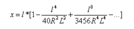
Parameter 'y':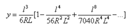
- Cubic - Select this to use an approximation to the clothoid spiral (above) where y is the current offset from the tangent, l is the current length along the spiral, R is the radius at the end of the spiral, and L is the total length of the spiral.
- Bloss - Select this to use an approximation where the transition angle θ:
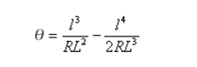
where l is the current length along the spiral, R is the radius at the end of the spiral, and L is the total length of the spiral.
This gives:
X = L – L^3/(43.8261*R^2) + L^5/(3696.63*R^4)
Y = (3*L^2)/(20*R) – L^4/(363.175*R^3)
where Y is the total offset from the tangent , X is the total distance along the tangent, R is the radius at the end of the spiral, and L is the total length of the spiral. - Korean Cubic Parabola - Select this to use a cubic parabola defined by the length of the parabola and the radius of the adjoining arc. The formulae for the 'x' and 'y' parameters in terms of these two values are as follows:
Parameter 'x':
This formula is the same as for the 'x' parameter of the clothoid spiral, reduced to the first term of the series.
Parameter 'y':
where y is the current offset from the tangent , x is the current tangential distance along the spiral, R is the radius at the end of the spiral, and L is the total length of the spiral. - NSW Cubic Parabola - Select this to use a special parabola used for rail projects in New South Wales, Australia. It is defined by the length of the parabola and a 'm' value. Refer to http://engineering.railcorp.nsw.gov.au/Disciplines/Civil/ESC_210_V4-3.pdf for the formulae for the 'x' and 'y' parameters for these two values.
- Railroad (chord) - Select this to use chord-based spirals (common in railway track alignments) for degree of curve and stationing calculations. Specify the default chord length in Project Settings > Units > Angular > Chord Length. This value is separate for meters vs. feet. (if you switch between meters/feet, each has its own value, rather than being converted). See the Spiral Type and Curve Type Combinations section below.
- Half-Sine (variable rate transition) - Select this to use a spiral that transitions from no change to a constant radius at a variable rate. The half sine spiral is useful for rail and other high-speed cases in which the vehicle cannot be steered (a clothoid spiral would make for a hard transition).
The formulae for the 'x' and 'y' parameters is: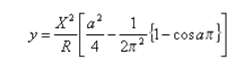
where a=x / X, x is the distance from the start to any point on the curve measured along the initial tangent, and X is the total X at the end of the transition.Caution! Due to the possibility of different implementations in other software products, you should confirm that your results match the original design and local standards.
Note: Spirals are linearized when they are sent to GCS, and chorded when exported as DXF format, which is a file format that does not support spirals of any kind. Alignments in XML files that are exported from Trimble Business Center define the type of spiral used.
- Clothoid (Euler) (constant rate transition) - Select this to use a common clothoid spiral defined by the length of the spiral and the radius of the adjoining arc. This is a spiral whose curvature/radius either increases or decreases linearly along its length. Clothoid spirals transition from straight to arc at a constant rate of change (inverse of the radius). In alignments, clothoid spirals are used to gradually spiral into a circular curve (arc segment) from a straight segment and then back out of the curve to another straight or circular curve segment. This is a good spiral for highway and other low to medium speed alignments and where vehicles can be steered within the width of the lane to make up for a less gradual radius change.
- Click .
The Alignment Editor displays, along with the Create Tunnel Corridor command pane.
- To enter a horizontal alignment's starting point:
- Double-click in the Station field of the POB (Point of Beginning) row and, using the values in your engineering design, type the starting station value.
- If necessary, enter (or select in a graphic view) values for the alignment's starting coordinate in the Easting and Northing cells.
Notes:
- When entering values, you can always right-click in the Plan View for COGO and snap options.
- You can right-click in the active cell to access Undo, Cut, Copy, Paste, and Delete commands, or right-click at the beginning of a row to access Insert Row, Delete Row, Copy, Alignment Project Settings, and Float View commands.
- If your engineering design shows values in a format different that the Alignment Editor is using, open the Project Settings dialog and click the Units link in the left navigation pane to change the display formats and entry methods. - If necessary, follow the steps in To add a segment or a curve at a PI in Edit a Horizontal Alignment.
When you create an alignment, you can specify whether its spirals use an arc- or chord-based definition for degree of curvature and stationing. Once the alignment has been created, you can also specify what type of definition to use for its arcs using the Properties pane. Then all station-related functions (snaps, exports, labels, explore object, station equations, and so on) reflect chord stationing.
Arc curve type
Chord curve type
Clothoid, etc. (arc) spiral type
default, usual
okay, but unusual
Railroad (chord) spiral type
okay, but unusual
default, usual
- Optionally, select the Station Eqn tab to add station equations.
A station equation is a numeric formula for the point on an alignment where the station value changes from one stationing scheme to another. A station equation may be used, for example, at the end of a horizontal curve to compensate for a design change in the radius of the curve, thereby adjusting the station values from the end of the curve onward to reflect their previously established values as occurring prior to the design change.
- To enter a vertical alignment's starting point:
- Click the Vertical tab.
- Click Create Vertical Alignment to make the cells available.
- Double-click in the Station box of the POB (Point Of Beginning) row and type the starting station value.
- Type the first point's elevation in the Elevation cell.
- Follow the stepsin Edit a Vertical Alignment.
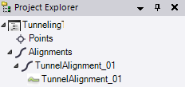
New horizontal and, if applicable, vertical tunnel alignment nodes display in the Project Explorer, nested beneath the parent Alignments tab.
You are now ready to create a tunnel corridor based on the new alignment.
