Apply a Cross-slope Rule
Cross-slope is an ‘arrow rule’ used to add a slope between locations on two lines, such as between the centerline and edge of pavement in a road cross-section. To apply it, specify a slope and then pick a beginning point on the first line and an end point on the second line. After you apply this rule, you can always edit other associated properties in the Properties pane.
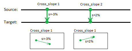
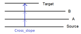
If a Cross-slope rule is correctly connected to lines, the start point will define the source line and the end point the target line. The cross-slope is always perpendicular to the source line, normally.
Cross-slope (and also Cross dZ) has special status as a rule. If cross-slope/cross dZ defines a connection between two lines, it also defines how the target line is computed (by derived computation) using a slope table referring to the source line. Since the source line must be 3D, vertical geometry is derived from the source line to the target line.
The Cross-slope rule makes it easy to control the slope value between a source line and a target line. By using this rule, slope can be set independent of the distance between the two lines. This means that if the distance changes, the vertical offset will change linearly.
Tip: To snap to the two lines, the Cross-slope rule uses the Hit length method to connect the lines (see “Connecting Rules to Lines”). When a cross-slope is correctly connected to source and target lines, the geometry of the rule is adjusted to match the required perpendicularity.
Note: Since cross-slope is defined to be perpendicular to source line, it can be slid along the source line. This is a powerful feature, because it is easy and quick to adjust the location of a cross slope along the lines.
You can create multiple cross-slopes between a source and target line as needed to make a smooth transition. The slope will transition from one rule to the next.
Create derived geometry by adding a single Cross-slope rule
A quick and easy way to create derived geometry from a 2D line is to attach a single cross-slope rule between two lines. The rule can be located wherever along the source line. The specified slope is extended to the beginning and end points of the line. The vertical alignment of the target line is derived from the source line’s vertical geometry with a constant slope value along the derived section.
Combining Cross-slope and Cross dZ rules in a Computation
You can combine several types of rules in same source/target computation. Cross-slope and Cross dZ rules can also be defined together. When computing derived geometry, every input has to be applied to the line.
Vertical designs have a property for setting how the vertical is computed from a source reference. This is called the linear change quantity (see “Vertical Design Properties”). The vertical can be derived either by slope linearity or by offset linearity. All rules connected to this computation are normalized in regards to this property setting: either slope linear or offset linear.
Warning: Be aware of this critical vertical design property as it may cause significant inequalities.
To apply a Cross-slope rule:
- Enter a Slope.
- Pick a point along the line (or enter a Start coordinate).
- Pick a point along the line (or enter an End coordinate).
- Write a Description of the rule.
- To place this rule above the previous, check the Insert above selected rule box.
- Click the Add Rule button.
- To change the calculation method, select the vertical design in the Project Explorer, and press [F11]. In the Properties pane, select a Cross-slope method option:
- Slope - Change the cross-slope to the derived target line linearly based on the elevation of the source line. Because the LSM least squares method (LSM) is used to compute the vertical curves, this method offers a high precision in how the slope changes linearly between source and target lines. The downside of this approach is that it can take a long time to compute, especially if linework is long, has a lot of spirals, or consists of many segments. As shown below, the types of rules applied between the lines (Cross-slope or Cross dZ) do not influence how the derived geometry is computed: the target line changes linearly by slope values that refer to the source line (slope linearity). All rules assigned to the target line are converted to slope values. An elevation value, for instance, is changed into slope values to be integrated in the derived computation.
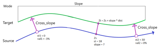
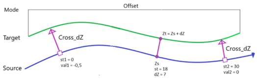
- Offset - Change the cross-slope to the derived target line linearly based on the elevation of the source line: the target line changes linearly by offset values that refer to the source line (offset linearity). For some geometric situations, this method is quicker than the Slope method, but it produces different result.
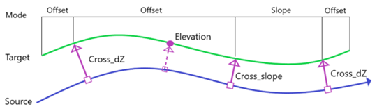
- Dynamic - Dynamic method includes both slope linearity method and offset linearity method in one: the right calculation method is automatically selected based on the type and location of Cross_slope or Cross_dZ rules applied to the target line. How the rules have an effect on which method is activated.
- Quick Mode - This method computes 3D points with a given density (point distance). All rules hitting the target line define a section for computing the 3D points, meaning that all hit point of any rules are computed to match input data. The Quick Mode method has an additional property: QuickmodeDensity (default value = 2.0 meter). This define the horizontal distance between the points. The Quick Mode method computes 3D points based on what Cross-slope or Cross dZ rule appears at the location of the 3D point. This can vary between the slope mode and offset mode, identical to how the dynamic modeselects between the two mode options, e.g., all 3D points are generated section-by-section (divided by all hitting rules at target line). For every section, the selected mode (slope or offset) is used to find correct elevation on the target line.
- Slope - Change the cross-slope to the derived target line linearly based on the elevation of the source line. Because the LSM least squares method (LSM) is used to compute the vertical curves, this method offers a high precision in how the slope changes linearly between source and target lines. The downside of this approach is that it can take a long time to compute, especially if linework is long, has a lot of spirals, or consists of many segments. As shown below, the types of rules applied between the lines (Cross-slope or Cross dZ) do not influence how the derived geometry is computed: the target line changes linearly by slope values that refer to the source line (slope linearity). All rules assigned to the target line are converted to slope values. An elevation value, for instance, is changed into slope values to be integrated in the derived computation.
Properties
- Description - Name given to the rule. When created, it is empty (blank). The name or description can be useful, in some cases, for understanding the order of the rules.
- Type - Cross-slope. This read-only property cannot be edited.
- Source line - Name of first of the two connected lines. If no line is connected, the property is empty (blank). The field is empty if the Hit length is smaller than the distance from the start point to the intersection point with the nearest line (source).
- Target line - Name of the second of the two connected lines. If no line is connected, the property is empty (blank). The field is empty if the Hit length is smaller than the distance from the end point to the intersection point with the nearest line (target).
- Slope - Slope (%) at the specified location of the rule.
- Apply to all crossing lines - If set to Yes, any lines (that are included in the vertical design) that are crossed/intersected between the source line and target line for this rule get the rule applied and are computed equally. If a locked 3D line is crossed/intersected, the line type cannot be changed, but it can be the source for elevation values for the rule. The line cannot be assigned a new vertical.
The property can intersect a line many times. The rule cannot connect the same line at both the beginning and end points.
When this property is applied to a Cross Slope rule, all lines are computed with equal slope value. Each of the lines is computed individually, based on its location to the source line and the slope value. Therefore, all lines together will define a constant sloped surface.
All lines are computed with equal rule properties. The vertical alignment of the source line is transferred to all target lines.
- Active - When created, this is set to True. If it is True, the rule is used in computations. Set this to False when you want this rule to be ignored.
- Order - Shows the order of the rule in the rules list.
- Status - Shows a code if there is an error computing the rule (or 0 (zero) if the status is okay).
- Message - If the Status=0, this property is blank. Otherwise, there is a message matching the status code.
