Apply a Cross dZ (cross delta elevation) Rule
Cross dZ is an arrow rule used to define a relative change in elevation between locations on two lines. To apply it, specify the delta elevation and then pick a beginning point on the first line and an end point on the second line. After you apply this rule, you can always edit other associated properties in the Properties pane.
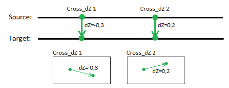
If a Cross dZ rule is correctly connected to lines, the beginning point will define the source line and the end point the target line.
Normally, the basic value of Cross dZ is the vertical offset value. Cross dZ is always perpendicular to the source line.
The Cross dZ (and also Cross-slope) has special status as a rule. If cross-slope/cross dZ defines a connection between two lines, it also defines how the target line is computed (by derived computation) using a slope table referring to the source line. Since the source line must be 3D, vertical geometry is derived from the source line to the target line.
The Cross dZ rule makes it easy to control the vertical offset value between a source line and a target line. By using this rule, vertical offset can be set independent of the distance between the two lines. This means that if the distance changes, the vertical offset remains unchanged.
Tip: To snap to the two lines, the Cross dZ rule uses the Hit length method to connect the lines (see “Connecting Rules to Lines”). When a cross dZ is correctly connected to source and target lines, the geometry of the rule is adjusted to match the required perpendicularity. Since cross dZ is defined to be perpendicular to the source line, it can be slid along the source line (like cross-slope can). This is a powerful feature, because it is easy and quick to adjust location of a cross dZ along the lines.
You can create as many cross dZs between a source and target line as needed.
Create derived geometry by adding a single Cross dZ rule
A quick and easy way to create derived geometry from a 2D line is to attach a single Cross dZ rule between two lines. The rule can be located wherever along the Source line. The specified delta elevation is extended to the beginning and end points of the line. The vertical alignment of the target line is derived from the source line’s vertical geometry with a constant slope value along the derived section.
Combining Cross-slope and Cross dZ rules in a Computation
You can combine several types of rules in same source/target computation. Cross-slope and Cross dZ rules can also be defined together. When computing derived geometry, every input has to be normalized.
Vertical designs have a property for setting how the vertical is computed from a source reference. This is called the linear change quantity (see “Vertical Design Properties”). The vertical can be derived either by slope linearity or by offset linearity. All rules connected to this computation are normalized in regards to this property setting: either slope linear or offset linear.
Warning: Be aware of this critical vertical design property as it may cause significant inequalities.
To apply a Cross dZ rule:
- Enter a Delta elevation.
- Pick a point along the line (or enter a Start coordinate).
- Pick a point along the line (or enter an End coordinate).
- Write a Description of the rule.
- To place this rule above the previous, check the Insert above selected rule box.
- Click the Add Rule button.
Properties
- Description - Name given to the rule. When created, it is empty (blank). The name or description can be useful, in some cases, for understanding the order of the rules.
- Type - Cross dZ. This read-only property cannot be edited.
- Source line - Name of first of the two connected lines. If no line is connected, the property is empty (blank). The field is empty if the Hit length is smaller than the distance from the start point to the intersection point with the nearest line (source).
- Target line - Name of the second of the two connected lines. If no line is connected, the property is empty (blank). The field is empty if the Hit length is smaller than the distance from the end point to the intersection point with the nearest line (target).
- Apply to all crossing lines - If set to Yes, any lines (that are included in the vertical design) that are crossed/intersected between the source line and target line for this rule get the rule applied and are computed equally. If a locked 3D line is crossed/intersected, the line type cannot be changed, but it can be the source for elevation values for the rule. The line cannot be assigned a new vertical.
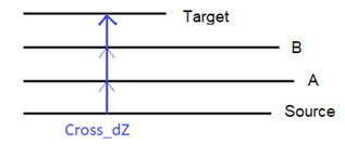
The property can intersect a line many times. The rule cannot connect the same line at both the beginning and end points.
When this property is applied to a Cross dZ rule, all lines are computed with equal vertical offset (Offset property of the rule).
- Vertical offset dZ - Vertical offset at the specified location of the rule.
- Active - When created, this is set to True. If it is True, the rule is used in computations. Set this to False when you want this rule to be ignored.
- Order - Shows the order of the rule in the rules list.
- Status - Shows a code if there is an error computing the rule (or 0 (zero) if the status is okay).
- Message - If the Status=0, this property is blank. Otherwise, there is a message matching the status code.
