Apply an Elevate by dZ (free delta elevation) Rule
Elevate by dZ is an arrow rule used to define a relative elevation change between any two points, whether on a line or not. Unlike the Cross dZ rule, it does not have to be connected to the source line, but it can.
To apply it, specify a delta elevation, and then pick or type in a 3D start point and an end point anywhere. After you apply this rule, you can always edit other associated properties in the Properties pane.
Note: For this rule to work correctly, the source point must be 3D (having an elevation). The computed elevation is applied to the target line based on the Hit length location.
The Elevate by dZ rule can connect to lines just like Cross dZ does. The only difference is that Elevate by dZ can also connect a beginning point to a 3D point.
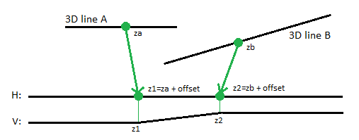
Figure: (represented in plan perspective above and profile below)
You can create as many 'free dZs' to a target line as needed.
To apply an Elevate by dZ rule:
- Enter a Delta elevation.
- Pick a point along a line (or enter a 3D Start coordinate).
- Pick a point along the line (or enter an End coordinate).
- Write a Description of the rule.
- To place this rule above the previous, check the Insert above selected rule box.
- Click the Add Rule button.
Properties
- Description - Name given to the rule. When created, it is empty (blank). The name or description can be useful, in some cases, for understanding the order of the rules.
- Type - Elevate by dZ ('free dZ'). This read-only property cannot be edited.
- Source line - Name of the first of two (possible) connected lines. If no line is connected, the property is empty (blank). The field is empty if the Hit length is smaller than the distance from the start point to the intersection point with the nearest line (source).
- Target line - Name of the second of the two (possible) connected lines. If no line is connected, the property is empty (blank). The field is empty if the Hit length is smaller than the distance from the end point to the intersection point with the nearest line (target).
- Apply to all crossing lines - If set to Yes, any lines (that are included in the vertical design) that are crossed/intersected between the source line and target line for this rule get the rule applied and are computed equally. If a locked 3D line is crossed/intersected, the line type cannot be changed, but it can be the source for elevation values for the rule. The line cannot be assigned a new vertical.
The property can intersect a line many times. The rule cannot connect the same line at both the beginning and end points.
The application of this property for the Elevate by dZ (Free dZ) rule is similar to its application to the Elevate by Slope rule (Free slope); it is just a point-based connection between the source line and the target lines. With this rule, all lines are elevated with equal offset. So, the surface will be a flat, horizontal surface.
- Vertical offset dZ - Vertical offset at the specified location of the rule.
- Active - When created, this is set to True. If it is True, the rule is used in computations. Set this to False when you want this rule to be ignored.
- Order - Shows the order of the rule in the rules list.
- Status - Shows a code if there is an error computing the rule (or 0 (zero) if the status is okay).
- Message - If the Status=0, this property is blank. Otherwise, there is a message matching the status code.
