Create and Publish a WorksManager Design for Earthworks
Use the Create WorksManager Design command to create a design for Trimble WorksManager. Then use the WorksManager Design Manager command to add design data (surface model, stakeout points, and design map objects), so it can be sent to field systems as a VCL file via WorksManager.
Models, which can be defined by a surface, an alignment, a surface and an alignment, 3D linework, and more, are used by crews in the field to:
- perform grading, checks, and other operations in Earthworks
- perform excavation and grading operations with machines in Earthworks
Multiple designs can be associated with a WorksManager project, and (unlike previous job site designs) the User-defined design model type can include multiple surfaces.
In WorksManager, you create a design by adding files with different kinds of data, but in TBC you create a design by picking objects within your TBC project data. This data is saved as part of the VCL and then published to the data synchronization area where it can be synchronized with WorksManager and picked up by Earthworks for use on the site. If needed, you can also copy project and design data to a USB flash drive to manually transfer them to machine control boxes.
Difference between Office > Office VCLs and Office > Field VCLs
When exchanging data between TBC projects using VCL import, ‘intelligent’ dependencies (and dependent objects) described above are retained.
When sending data from TBC to field systems as designs (that the firmware opens) via WorksManager, dependent objects for surfaces and road surfaces (e.g., the points and lines that define them) are not included. Typically, those objects are not needed for field work, and eliminating them makes the VCL files much smaller and usable by the field devices and machine controllers.
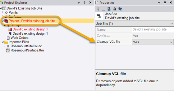
This behavior is controlled by the Cleanup VCL file property in TBC. By default, this property is set to Yes for WorksManager projects. To change the setting, click a WorksManager project in the TBC Project Explorer, press F11 to open the Properties pane, and change the Cleanup VCL file property. Then, dependent objects will once again be sent to the field in VCL designs when using WorksManager as the intermediary.
Note: TBC cannot currently detect if new designs are created in WorksManager (not TBC), so the only way is to bring them into your TBC WorksManager project is to download them manually from WorksManager and, then import them into your TBC project.
Tip: After you have created one or more WorksManager designs, if you modify the data that those designs reference, you can use the Publish Designs to WorksManager command to resynchronize all of the designs with WorksManager at once.
Prerequisites:
- License; See the Subscription Plans page. For a license matrix by command, see the License page in the TBC Community. Also see View and manage licensed features.
- Trimble Identity (TID) credentials (user name and password); create it here.
- WorksManager account; contact your SITECH dealer for details.
- In TBC, you are signed in to WorksManager using your TID
- Specified data synchronization area
- A WorksManager account that has been configured in External Services
- For existing WorksManager projects, access to them (granted by the people who created them)
- A WorksManager project created in Open WorksManager and Create a Project
Note: In the WorksManager Design Manager, invalid objects (e.g., point cloud regions, coordinates/occupations, scan stations, etc.), are ignored if you try to add them to the design map. The results message beneath the select control indicates how many objects were ignored.
To access the command:
- SelectCreate WorksManager Design in Construction Data > WorksManager.
- Right-click a WorksManager project or its Designs node in the Project Explorer and select Create WorksManager Design from the context menu.
- To edit an existing WorksManager design, right-click it, and select WorksManager Design Manager.
To create a design for a WorksManager project:
- If needed, click Switch Account to select a different WorksManager account or to work offline.
- In the Create WorksManager Design command, type a unique name in the Design name box.
- Click OK. The WorksManager Design Manager command pane displays, and the design appears in the Project Explorer.
- When you are first creating a design (before it has been published) the version shows <Not Saved>. If you are editing an existing design, confirm its version number. Versioning of the design helps keep the design in TBC synchronized with the design in WorksManager (via the data synchronization area). File versions displayed here help you (and supervisors in the field) ensure that the project contains the most recent data.
- Click Change Model and choose one of these options for the design model:
- None - This type is selected by default.
- Surface - Select this to specify only a surface and an optional clipping boundary for the model. If the surface used in your design model is clipped by a boundary, all breaklines in the surface will appear as unnamed features when the surface is viewed in Siteworks. If the surface in your design model does not contain a boundary, the breakline names will appear in Siteworks.
- Alignment - Select this to specify one or more alignments for the model.
Note: The alignment model can be made from 3D alignments defined by a HAL and a VAL, and 2D alignments defined by a HAL alone (if either no VAL exists or more than one VAL exists). This will enable field crews to stake the alignments, or others generated 'on-the-fly' in relation to them, based on a combination of horizontal offset, vertical offset, and cross-slope in Siteworks.
- Road surface - Select this to specify a surface, optional boundary, and one or more alignments for the model.
Note:For a road surface model, the alignment and surface you select must be coincident.
Note: If the design is for Earthworks, only one alignment can be selected. You can export named sub-alignments to Earthworks machines, enabling you to see a corridor's named cross-section nodes.
Note: Two settings control how surface cross-sections are generated and displayed in this software. These settings are not available in Earthworks. Therefore, when a road surface is exported to Earthworks, the cross-sections in the field software may be different than those in this office software. For a detailed explanation of the difference and its ramifications on grading a road, see Differences in Road Surface Models between TBC, GCS900, and SCS900 in the Trimble Community. - 3D linework - Select this to pick 3D lines for the model.
Note: For Earthworks, 3D linework is typically used for digging trenches with an excavator or guiding a grader in grading a road using a simple cross-slope.
- Material layer - Select this to specify a corridor surface, optional boundary, an area-based site improvement (e.g., road base course), and specific material layer within that site improvement, e.g., crusher fines).
- User-defined - Select this to pick other types of objects for the model.
- Skip the Stakeout Points group. Earthworks does not use points in designs.
-
 Click +/- to display the Add/Remove Design Map Objects dialog, in which you can change the map objects included in the design data.
 - Pick design or background map objects in a graphic view.
- Select - Click this to highlight the map objects currently included in the design data.
- Click Publish to push the design to WorksManager. Also see Publish Designs for WorksManager.
- Click Close.
To delete a project design:
- Right-click the design in the Project Explorer and select Delete.
