Apply a Crest/Sag Rule
Crest/Sag is a ‘point rule’ used to add a specific elevation to a 2D line where you want an apply a high/low point to make the line 3D. To apply the rule, specify an elevation and vertical radius, and then pick a location along the line (where grade = 0%). The position of the rule might change slightly when computed because the program does not know exactly where grade is 0%. This rule is similar to Vertical PI rule, but just with a different computation. After you apply this rule, you can always edit other associated properties in the Properties pane. The type of vertical curve used is determined by a property of the vertical design.
When you want to create vertical geometry for an alignment/linestring, you typically want to use the Vertical PI rule. However, using that rule can make it difficult to precisely specify the exact elevation of the line because the elevation property represents the point of intersection (of tangents) and not the line itself. The Crest/Sag rule gives you an alternate method for representing the exact elevation of a crest or sag on the line.
If rules applied to the same target line are adjacent in the list of rules, the order is not important. All rules attached to the same line are sorted when the VAL is computed.
Tip: When adding the crest or sag elevation by picking a line, the rule uses the Search distance to snap perpendicularly to the nearest line within the search tolerance. If no line matches this requirement, the rule is not applied and you receive an error message.
Note: Currently, overlaps of multiple Vertical PI or Crest/Sag rules may cause a problem.
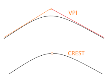
Figure: Specifing a vertical curve with the Vertical PI rule versus the Crest/sag rule
To apply a Crest/Sag rule:
- Enter an Elevation for the crest or sag.
- Enter a Vertical radius or pick two points along the line to specify it.
- Pick a point along the 2D line (or enter a Start coordinate) for the location of the crest or sag.
- Write a Description of the rule.
- To place this rule above the previous, check the Insert above selected rule box.
- Click the Add Rule button.
Properties
- Description - Name given to the rule. When created, it is empty (blank). The name or description can be useful, in some cases, for understanding the order of the rules.
- Type - Crest/sag. This read-only property cannot be edited.
- Target line - Name of connected line. If no line is connected, the property is empty (blank). If no line is connected, the property is empty (blank). The field is empty if the Search distance is set smaller than appearing offset distance from elevation point to nearest line in project.
- Elevation - Elevation at the specified location of the rule.
- Radius - Vertical radius at given location (VPI) of the rule.
- Active - When created, this is set to True. If it is True, the rule is used in computations. Set this to False when you want this rule to be ignored.
- Order - Shows the order of the rule in the rules list.
- Status - Shows a code if there is an error computing the rule (or 0 (zero) if the status is okay).
- Message - If the Status=0, this property is blank. Otherwise, there is a message matching the status code.
