Automatically Set Z-Values Where Lines Connect in a Vertical Design
Enable the Automatic Z-values property to maintain the integrity of a vertical design by automatically giving connected lines the same elevations (z-values) where they touch (via a 'virtual'connector). In other words, if you add an Elevation rule (for example) to a connected series of unelevated (2D) lines, they will all be elevated to the elevation of that rule. This option is set per vertical design in your project.
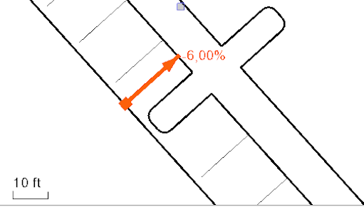
Figure: A baseline and several connected lines that have been automatically raised to the baseline's elevation via an Elevation rule and the Automatic Z-values property.
Using Connector rules versus the Automatic Z-Value property to copy elevations
With a Connector rule, you can explicitly define which line is dominant. The Automatic Z-Value property, in contrast, streamlines work if you have a lot of intersection/touching lines and there is no question from which line the elevation should be derived. In certain cases (e.g., overlapping lines), the Connector rule will give you more accurate results. See Apply a Connector Rule for details.
Ways to access:
- When you are creating or editing a vertical design, check the Automatic Z-values box on the Rules tab.
- Otherwise, you can press [F11] to open the Properties pane, and change the Automatic Z values property to Yes.
Important Auto Z-value notes:
- Virtual connectors (such as Automatic Z-value) are applied after all standard vertical design rules are calculated; all linework is computed first. To find virtual connectors, two lines must intersect (or touch at begin/end points or somewhere on an arc). If both of the lines are already 3D and locked, no virtual connector is applied at the intersection.
- If all requirements are fulfilled, a connector with the correct elevation is created and attached to the target line. It is also possible to choose Elevation instead of Connector; either rule works.
- Because connectors are virtual, they are not visible and do not show a Status code. Therefore, any errors are shown as messages in the Flags Pane.
- Lines have an order (shown in the table) that indicates their priority in calculations. This order cannot be directly edited in the list, but you can affect the order by removing and re-adding lines to place them last in the list. If two or more lines are equal (it is not clear which one is dominant), then the one that has the smaller order number is dominant. Order remains the same between sessions.
- If a line intersect itself, the z-value of the smaller station location of the line is dominant.
To change the order of lines:
- In the Edit Vertical Design command, click the Lines tab.
- Select one or more lines in the list and click the Remove Lines button.
- Re-add each line to the vertical design by selecting it in a view and clicking the Add Lines button. Each line is added to the bottom of the table on the Lines tab. This is the only way to re-order lines.
General rules for the calculation priority of elevated lines:
When two 3D lines with different elevations intersect, the dominant line (which sets the merge elevation) is determined by:
- Locked 3D lines are strongest (Level 1). No intersecting points on a locked line can be changed.
- Lines updated/computed using rules are the next strongest (Level 2). If a (2) line intersects with a higher level (1) line, the elevation from (1) is used. If a (2) line intersects with an equal level (2) line, the order in the line table determines which is dominant.
- All other lines in a vertical design are the third strongest (Level 3). If a (3) line intersects with higher level (1 or 2) line, the elevation from the (1 or 2) line is used. If a (3) line intersects with an equal level (3) line, the order in the line table determines the dominance.
