Create a Vertical Design
Use the Create Vertical Design command to build models from linework using a variety of rules (parametric instructions) for elevations, slopes, cross-slopes, grades, and other types of connections and transitions. This functionality provides a rule-based way to create 3D models for roads, intersections, parking lots, landscaping, and other site features.
To quickly and easily add one or more vertical design rules to a line or between two lines without needing to use this command, use the Create Global Vertical Design command.
Prerequisites:
- License; See the Subscription Plans page. For a license matrix by command, see the License page in the TBC Community. Also see View and manage licensed features.
- 2D or 3D lines, linestrings, and/or alignments
To access the command:
- Select Create Vertical Design in Data Prep > Lines.
To create a vertical design:
- From the Lines and linestrings box, pick all of the linear objects you want to use for the design in a graphic view, or click Options for more selection methods. Typically, it works best to create your vertical design in Plan View and have a 3D Viewopen next to it to check how the model is being formed.
Tip: The number of lines used in each vertical design should be generally a dozen or less. Large numbers of lines will cause the surface to be created more slowly.
- Enter a descriptive Name for the vertical design, such as intersection or curb-and-gutter.
- Click Apply to create the design, which will appear in the Project Explorer. A flag appears on one of the lines in the design to make it easier to select the design. The Edit Vertical Design pane also opens.
- Follow the steps in Edit a Vertical Design.
Dependencies:
Each vertical design is dependent on the lines and alignments it was built from; if you edit the geometry of any, the design updates accordingly.
Vertical Design Properties
Vertical designs have these editable properties which you can access by selecting the design and pressing [F11] to open the Properties pane.
- Name - Give each design in a project a unique name to make it easier to distinguish them from each other. Names are required for vertical designs.
- Rebuild method - parametric vertical design can be run by several options;
- Auto - This is the default setting that allows the design to rebuild automatically after each change that affects it.
- Show empty - Select this to hide the resulting design surface in graphic views while you make edits. The surface cannot be automatically or manually rebuilt in this state.
- By user - Select this to suspend the process of rebuilding the surface until you select Rebuild in the Edit Vertical Design pane or by right-clicking the design in the Project Explorer and selecting Rebuild Vertical Design.
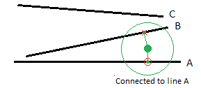
- Search distance - For point rule types (Elevation, Vertical PI), if the point location is this close to a line included in the design, the rule is applied to that line. Enter a distance that is large enough to find the applicable line, but small enough to exclude other lines. This is analogous to a pick aperture.
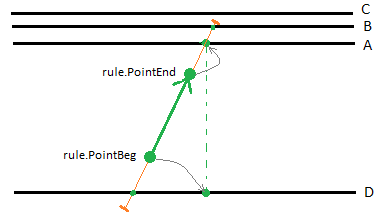
- Hit length - For arrow rule types (Elevate by Slope, Elevate by dZ, Cross-slope, Cross dZ), if the vector created by the start and end point is extended this far to a line included in the design, the rule is applied to that line. Enter a distance that is large enough to find the applicable lines, but small enough to exclude lines outside the design.
- Vertical curve - Select whether to create vertical curves in the design using an arc or a vertical parabola (only symmetrical parabolas are supported).
