Add and Remove Image Boundaries
Use the Add/Remove Image Boundary command to mask portions of one or more imported images by adding a boundary (boundary or polyline) to them. This is helpful when you need to edgematch multiple plan sheets or images of a job site. Only one boundary can be applied to each image, but many images can be clipped by each boundary. Because only one boundary can be applied to an image, image holes and islands cannot be created. Boundaries added to an image limit the image's visibility in graphic views, but they do not clip (delete) the image data. Image boundaries do not affect images in the 3D View.
Tip: To edgematch two images using a single boundary, mask the image on top/in front of the other image in the view priority. You can determine and change the view priority in the Properties pane for each image. You can also make the top/front image semi-transparent (see Image transparency below).
Tip: Remove borders from images (such as USGS map sheets) before you import, georeference, and use this command to edgematch them.
|
|
|
|
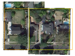
Two georeferenced images and two boundaries |
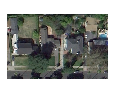
Images with the orange boundary added to the one on the left and the yellow boundary added to the one on the right (and boundaries then hidden) |
Prerequisites:
- License; See the Subscription Plans page. For a license matrix by command, see the License page in the TBC Community. Also see View and manage licensed features.
- One or more imported and placed or georeferened images
- One or more polylines (either open or closed) with at least two segments that are coincident with one or more images in the Plan View
To access the command:
- Select Add/Remove Image Boundaries in CAD > Images.
- Right-click an imported image in the Project Explorer and select Add/Remove Image Boundaries from the context menu.
- Right-click a boundary and select Add/Remove Image Boundaries from the context menu.
The Add/Remove Image Boundaries command pane displays.
To add or remove an image boundary:
- Check the box for each image that you want to mask with a boundary line in the Target images list.
- To mask an image, click in the Clipping boundary box and pick the polyline that you want to use as the image boundary in the Plan View. Linestrings, polylines, alignments, and boundaries can be used as the clipping boundaries. Objects used to limit an image can be either 2D (such as boundaries and alignments without VALs) or 3D (such as 3D linestrings or alignments with VALs).
- Click to mask the image based on the selected boundary. The image is masked in the Plan View. The image icon also changes in both the command pane and in the Project Explorer, and the name of the boundary appears next to the image name in the Target images list.
Note: Image masking appears in both the Plan View and in the 3D View (if the image has been applied to a surface and a boundary's extent's are smaller than that of the surface).
- If needed, repeat steps 1 - 3 to add another boundary to different images.
- To remove a boundary from an image, check the box for the image and click Remove instead of Add. The original extents of the image are revealed in the Plan View.
Note: You can also remove a boundary from images by deleting the polyline being used as the boundary.
- Click .
Note: If you add a second boundary to an image, the first boundary is replaced by the second.
Note: If you add a boundary to an image that it is not coincident with, the image is still considered clipped (as the image icon conveys).
Image transparency:
You can specify the transparency of an image in the Properties pane for the image. In the Transparency box, specify a percentage (0 = opaque; 100 = completely transparent/invisible).
Image icons:
When you import image files, their icons can help you identify what type of data they contain.
|
|
|
|
|
Vector image/PDF |
Similarly, when you use the Add/Remove Image Boundaries command to mask portions of images, their icons change to indicate that part of the image has been hidden.
|
|
Raster image to which boundaries have been added |
|
|
Vector image to which boundaries have been added |
Scenarios:
- When you re-georeference an image to which a boundary has been added, the entire image is redisplayed until you click Compute to apply the transformation.
Dependencies:
- The image and its boundary are interdependent. If you move the boundary in relation to the image, a different portion of the image is masked, and vice versa (if you re-georeference the image in relation to the boundary, a different portion of the image is masked; images cannot be moved using the Move Objects command.).
