Identify Simple Subgrade Adjustment Regions
Use the Identify Site Regions command to create simple subgrade adjustments between the Finished design surface and the FD with subgrades adjusted surface to represent the space and volumes that will be occupied by actual area-based site improvements. This enables you to form the Finished with subgrades adjusted surface without having to create specific area-based site improvements and their individual material layers.
This feature is helpful if you are an earthmoving contractor who is not involved in constructing pavements, buildings, sidewalks, or other site improvements; it allows you to skip the definition of site improvement material layers if you are not involved with building the subgrades above the mass earthworks level.
Note: When you assign simple subgrade adjustments, they are shaded in this command and the Configure Subgrade Adjustments command.
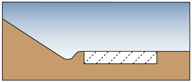
Figure: Cross-section representing a simple subgrade adjustment and FD with subgrades adjusted surface
Prerequisites:
- Licensed module; See the Subscription Plans page. For a license matrix by command, see the License page in the TBC Community. Also see View and manage licensed features.
- Layers that have been categorized and identified as containing potential boundary lines in the Categorize Takeoff Layers command
To access the command
- Select Identify Site Regions in Takeoff > Site Improvements.
To assign simple subgrade adjustments to site regions:
- In the Takeoff Category group, select the Design category (which contains the layers you designated as having potential boundaries for area-based site improvements).
Potential boundaries are highlighted orange. Lines that are not identified as potential site improvement boundaries are visible, but not highlighted.
Note: If area-based site improvements or simple subgrade adjustments have already been associated with site regions (using either this command or the alternate method within the Categorize Takeoff Layers command), they appear shaded when you select their category. For details on the differences between the two methods, see Understanding Area-based Site Improvements.
- To find any gaps that might be occurring in the boundaries you want to use for subgrade adjustments and which may be preventing the desired site region from being formed as an enclosed area, check the Highlight all potential boundaries box. Doing this highlights in a magenta color, any portions of lines that have been identified as potential boundary lines, but which cannot be used to form site regions, perhaps due to their failure to intersect other such potential boundaries.
- Select the layer on which you want the subgrade adjustment's 'seed point' to reside in the Layer list, or select <<New Layer>> to create a new layer for it. The color of the layer does not affect the subgrade adjustment's fill color.
Note: You should avoid putting subgrade adjustment seed points on layer categorized as Design; you do not want them to contribute to the formation of finished design surfaces.
Note: If you find the Layer list disabled (grayed out), change the Action option below from Remove identity to Identify region. - Confirm that Identify region is selected.
- Scroll down and expand the Simple Subgrade Adjustments section.
- Select a Subgrade adjustment type:
- Planinemtric/vertical - Select this for relatively flat regions for which you just need to calculate a vertical depth. This applies to most needs.
- Surface/perpendicular - Select this for subgrade adjustments on steeply sloped areas, e.g. hillsides and ditch lines, for which you want to calculate a perpendicular depth.
- Click in the Location box and pick a point (in the Plan View) within the site region that you want the subgrade adjustment to fill. You must pick a location encompassed by the highlighted lines. An indicator (dot) appears at the location, and the region is shaded with a color (50% transparent).
- If needed, repeat steps 6 and 7 to add more subgrade adjustments. Your goal is to shade all the regions that would contain area-based site improvements.
- Click Close when you are done. The shading is hidden until you run the command (or another command that shades subgrade adjustments) again.
- Use the Configure Simple Subgrade Adjustments command to specify or edit the total thicknesses for each subgrade adjustment.
To remove a simple subgrade adjustment:
- Click Remove identity in the Site region identification group.
- From the Location box, pick in the shaded region from which you want to remove the subgrade adjustment. The shading and seed point disappear, indicating that the subgrade adjustment has been unassigned from that region.
Note: Use Explore current region (described below) to avoid accidentally removing site improvements instead of subgrade adjustments.
Options:
- Location - In this coordinate control, specify the seed point from which the site improvement and shading will spread until it reaches a highlighted boundary line.
- Explore current region - When your cursor is in the Location box, hover over any shaded region in the Plan View to see the identity of the subgrade adjustment or site improvement that is assigned to it in this box.
- Gap closure tolerance - This displays the distance that boundary lines will be extended to close unintended gaps, as may be needed to form enclosed site regions. To change the tolerance, click the Project Settings icon on the pane's toolbar to open the Project Settings dialog. This lets you accommodate small errors in digitized data, or typical CAD data resulting from inattentive operation.
Note: The Gap closure tolerance is a global setting applied to all areas each time the Identify Site Regions or the Track Region Outline command is run. Changing this setting may affect previously assigned subgrade adjustments, by altering their boundaries, and may result in flags being presented as the resulting site regions may then contain multiple site improvement or subgrade adjustment objects. Unless you just want to perform a quick takeoff without investing in data preparation, you are probably better off fixing the geometric problems in the data by editing the lines that have not been recognized as contributing to the bounding of a site region, but which should have done so. The lines that need attention, are often those that have been highlighted in a magenta color by checking the Highlight all potential boundaries box.
Scenarios:
- If you change the lines on which a subgrade adjustment's region is based, the subgrade adjustment may move to another region (based on the seed point's location) and be flagged as an error.
Dependencies:
- The extents of a subgrade adjustment's region are dependent on the designated lines that encompass it. If you edit those lines and the seed point still lies within a site region, the subgrade adjustment's region is updated.
