surface (generalized and composite) properties
Note: This topic describes just the more important, confusing, or complex properties.
|
Surface (generalized) |
|
|
(includes common properties for layer, subgrade, topsoil, and uncompacted PCS surfaces) |
|
|
Surface |
|
| Surface classification |
See Surface Options for details. |
| Horizontal alignment Alignment-based |
See corridor properties. |
| Maximum edge length |
This shows the maximum triangle edge length allowed on this surface as defined in Project Settings > Computations > Surface> Surface Creation Defaults. |
| Maximum edge angle |
This shows the maximum outer angle allowed at vertices on this surface as defined in Project Settings. |
| Adjust 'flat' triangles |
Select Yes to adjust triangles to remove 'flat' triangles from contour source data. |
| Tolerance |
This shows the distance within which duplicate vertices will be moved to prevent 'flat' triangles from forming. |
| Display flags |
Show/hide warning flags. |
| Rebuild method |
Select an option for how and when to update the surface after changes have been made:
Tip: Since this option decreases your project's file size, it is a good one to select before you send your project to a colleague. Remember to have them reset the surface to Auto after they open the file.
|
| Transparency |
Enter the transparency percentage for the surface (0 = opaque; 100 = completely transparent/invisible). Increasing a surface's transparency can help you see other objects that lie under it in graphic views. |
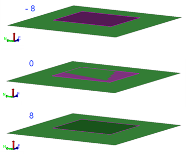
| Face Displacement |
When you have a shaded surface triangle (filled polygon/3D face) draped above another shaded surface triangle, use this setting to raise or lower (displace) the draped 'face' to prevent the surface color of the lower face from showing through the higher face. Changing the displacement value is purely graphical and has no effect on either the surface's or face's elevations. This example shows one surface above another, with a face displacement (on the purple surface) of -8, 0, and 8.
|
| Measured date |
Date when the surface members were surveyed. |
| Shade by slope range |
Display only triangles that have a slope within a specified range. See Shade Surface Triangles by Slope Range for details. |
|
Show in Plan View Show in 3D View |
|
| Backfaces |
Yes - Select this to make the surface visible from beneath, this makes the back of each 3D face (backface) opaque. No - Select this to make the surface invisible from beneath, this makes the back of each 3D face transparent. |
| Wireframe |
Select Yes to make each triangle edge visible. |
| Vertices |
Select Yes to make each vertex visible in the applicable graphic view. |
| Breaklines |
Select Yes to make each breakline visible in the view. |
| Drapelines |
Select Yes to make each drapeline visible in the view. |
| Show slope arrows |
Select Yes to see the slope direction of each triangle in the surface. To specify the length of the slope arrows, select Project Settings > Computations > Surface> General. Change the value in the Slope arrow length box. |
| Show shadows |
Display shadows on the surface. |
| Shading |
Note: If you drape an image on a surface or use an image as a surface material texture, select this setting for each graphic view in which you want to see the image.
|
|
Densification |
|
| Densify surface |
See corridor properties. |
|
Summary |
|
|
Number of independent vertices |
Vertices which belong only to the surface and are not generated from an external object (surface member).. |