Create and Edit Dimension Styles
Trimble Business Center allows you to create dimensions for both lines (based on point pairs, line segments, and arc segments) and angles (based on either two lines or an arc segment). When creating a dimension, you must specify the dimension style you want to use as a template to format the dimension.
Trimble Business Center includes a default "Standard" predefined dimension style you can modify or use to create additional dimension styles.
Note: To ensure that the size of dimensions or labels is correct when viewed in the Plan View, verify that the plot scale for the project is set correctly in Project Settings > View > Plan View. The plot scale is the factor used to convert from ground units to sheet units (ground units / plot scale = sheet units). For example, if the default plot scale of 600 is used, an object with a length of 600 m in the Plan View will plot with a length of 1 m on paper. In survey feet, the default plot scale of 50 will plot as 1 foot on paper.
Prerequisites:
- Licensed module. See the Subscription Plans page. For a license matrix by command, see the License page in the TBC Community. Also see View and manage licensed features.
To create a new dimension style:
- Select Dimension Style Manager in Drafting > Dimensions.
- In the Dimension Style Manager dialog, click the New button.
- In the Create New Style dialog, do the following:
- Enter a name for the new dimension style.
- In the Copy from drop-down list, select an existing style on which the new style will be based.
The properties for the selected existing style populate the fields on each of the four tabs. You can edit any of the properties as described in the following procedure.
- Click OK.
The new style name is displayed in the Dimension Styles list and in the Style name field.
To edit a dimension style:
- If the Dimension Style Manager dialog is not already open, select Dimensions Style Manager.
- In the Dimension Styles list, select the dimension style you want to edit.
- Optionally, change the name of the style in the Style name field.
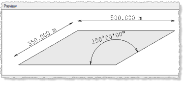
An example preview of the dimension style is displayed on the Preview tab. As you make edits to the style, they are reflected in the preview.
- To edit the lines used in the dimension, select the Lines tab.
- Dimension Lines - Select the direction and relative location of the dimension arrows, or select Automatic to specify that the software determine the direction. Following are examples.
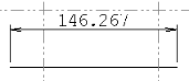
Automatic or Always outward arrows option selected when the dimension text fits on the dimension line:
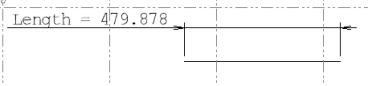
Always outward arrows option selected when the dimension text does not fit on the dimension line:
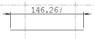
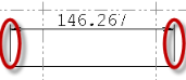
Always inward arrows option selected when the dimension text fits on the dimension line:
Automatic or Always inward arrows option selected when the dimension text does not fit on dimension line (it is offset to the left or right, depending on the direction you move your cursor):
- Extension Lines - Select whether or not to create extension lines at the start (Extension line 1) and end (Extension line 2) of the line.
- Dimension Lines - Select the direction and relative location of the dimension arrows, or select Automatic to specify that the software determine the direction. Following are examples.
- To edit the arrows used in the dimension, select the Arrows tab.
Select the arrow head style and size to be used at the start (Arrow 1) and end (Arrow 2) of the line. You can also choose to have no arrow heads.
- To edit the text used in the dimension, select the Text tab.
- Dimension Text - Select a text style or select <<New Style>> to display the Text Style Manager where you can create a new text style. Also, select the position for the text (relative to the dimension line), and its orientation. Following are orientation examples.
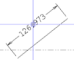
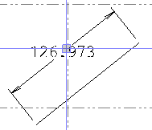
Aligned orientation selected:
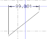
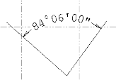
Level orientation selected:
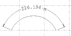
Aligned with arc orientation selected:
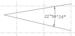
Perpendicular orientation selected:
Note: Dimension text aligned with its dimension arc will be divided into individual characters when the project is exported to a DXF/DWG file.
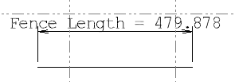
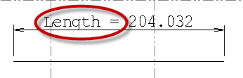
- Linear Dimension Text - Optionally enter prefix or suffix text for the dimension label. Following is an example.
Prefix added:
- Dimension Text - Select a text style or select <<New Style>> to display the Text Style Manager where you can create a new text style. Also, select the position for the text (relative to the dimension line), and its orientation. Following are orientation examples.
- To edit the distance units used in the dimension label, select the Distance tab.
Select the Use Project Settings check box to use the default project settings for all of the other Distance Unit settings. Otherwise, deselect the check box and manually enter settings. For more information about distance unit settings, see Unit Settings.
Select the appropriate Unit style. If you select Decimal, you can specify a unit of measurement. If you select Engineering, the unit of measurement is Foot only (displayed in decimals). If you select Architectural, the unit of measurement is Inch only (displayed in feet, inches, fractions of inches).
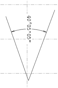
- To edit the angular units used in the dimension label, select the Angular tab.
Select the Use Project Settings check box to use the default project settings for all of the Angular Unit settings. Otherwise, deselect the check box and manually enter settings. For more information about angular unit settings, see Unit Settings.
- To edit the dimension position, select the Position tab.
If necessary, make changes to the dimension text offset, dimension line length, dimension line stretch, extension line offset, and extendension line stretch. Use the image on the tab as a reference for the different position settings.
Dependencies:
- Dimensions you create in your model are dependent on their dimension style, but if you change the style existing instances of the dimension are not updated.
