Create and Edit Label Table Styles
Trimble Business Center allows you to create and display in the Plan View and Sheet View a table from selected points, lines, and polygons that automatically enumerates their attributes based on the selected label table style. You create, edit, and delete label table styles using the Label Table Style Manager dialog.
A label table style specifies the type of information to be displayed in each column in the table. For example, in a label table intended for line segments, you might include one column each for the length, azimuth, and slope of the segment. Then, when you create a table using the style, each selected line segment will be included as a row in the table with the specified information displayed in each of the columns.
A label table style also specifies the display of text in the table (including the formatting of angles and precision, the use of unit suffixes, and text justification) and the appearance of the table itself (including text styles and table borders).
Note: To ensure that the size of dimensions or labels is correct when viewed in the Plan View, verify that the plot scale for the project is set correctly in Project Settings > View > Plan View. The plot scale is the factor used to convert from ground units to sheet units (ground units / plot scale = sheet units). For example, if the default plot scale of 600 is used, an object with a length of 600 m in the Plan View will plot with a length of 1 m on paper. In survey feet, the default plot scale of 50 will plot as 1 foot on paper.
Prerequisites:
- Licensed module. See the Subscription Plans page. For a license matrix by command, see the License page in the TBC Community. Also see View and manage licensed features.
To create a new label table style:
- Select Label Table Style Manager in Drafting > Tables and select the tab for the type of label table style you want to create.
- Click the New button.
- In the Create New Style dialog, enter a name for the new style, select an existing style on which to base the new style, and click OK.
The properties for the existing style are applied to the new style. You can edit the properties as described in the following steps.
The new label table style is displayed in the Label Table Styles list.
- Do any of the of the following as necessary to specify the columns to include in the label table using the Column fields list:
- To remove any columns currently displayed in the column list on the Label Type tab (that is, remove them from the label table), select each column you want to remove and click the Delete button located above the list.
- To add columns to the column list (that is, add them to the label table), select each column you want to add in the Column fields drop-down list and click the Add button.
Notes:
- If you select a column field that displays a ground distance, the Define Scale Factor button activates when you click the Add button. You can click the Define Scale Factor button to display the Labeling Scale Factor dialog, which allows you to define a combined scale factor to be used to convert grid distances to ground distances displayed in segment labels. See Define a Labeling Scale Factor for more information.
- If you add a column field type that displays an ellipsoid distance, the settings in the Labeling Scale Factor dialog do not apply because this dialog only applies to ground distances.
- You can use the User Defined Attributes column field type to specify the feature attributes you want to include in the label table style. See Select Feature Attributes to Include in Labels for instructions. - To rearrange the columns in the column list (that is, rearrange them in the label table), select each column you want to move and use the arrow keys located above the list as appropriate. The top column name in the list represents the first (left-most) column in the table, the second column name in the list represents the second column in the table, and so forth.
- Do either or both of the following, if applicable:
- If you selected to add the Station and/or Offset field to the label table, select the Alignment to reference. The Station and Offset values displayed in the label are based on the closest point on the selected alignment's centerline to the labeled point.
- If you selected to add the Surface Elevation and/or Delta Surface Elevation to the label table, select the Surface to reference. A point must be located within the 2D boundary of the selected surface to support these label types. The Surface Elevation value displayed in the label is the elevation of the surface at the 2D position of the selected point. The Delta Surface Elevation value is the elevation difference between the labeled point and the nearest point on the selected surface.
- To edit the way content is displayed in any of the label table columns, on the Label Type tab select the column in the list and make changes in the fields located beneath the list as necessary. (Note that some fields may not be available based on the selected column field type.)
- Column text – Change the column header text displayed in the top row of the column.
Note: If you want to use the User Defined Attributes column field type to specify just the feature attributes you want to include in the label table style, you will need to enter text in the Column text field as described in Select Feature Attributes to Include in Label Tables.
- Display units suffix – Select whether to include a units suffix in the data, or select to use the default setting for displaying unit suffixes specified in Project Settings > Units.
- Precision – Select the decimal precision to use for the data, or select to use the default precision specified in Project Settings > Units.
- Angle display – Select the angle display format for the data, or select to use the default format specified in Project Settings > Units.
- Text justification – Specify the placement of the data text in the column. (This does not affect the justification of the column header text, which is addressed later in this procedure.
- Column text – Change the column header text displayed in the top row of the column.
- Check the Flip lab automatically flipped to the opposite offset, as long as that offset is empty checkbox to move overlapping labels to the opposite offset. Note that the label will not be flipped if there is any data in the opposite offset.
- Select the Border tab to edit the line color, style, and/or weight for the entire table and various sections of the table.
- Select the Text tab to edit the text style, color, gap (between the text and the cell border), and justification used for the table title, column headers, and data.
Note that the Text justification field is not available for data text since it was specified on the Label Type tab.
- Select the Sort tab to specify the sort order for data displayed in each of the columns.
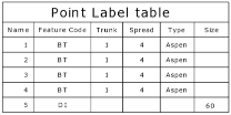
- Optionally, check the Separate attributes into their own columns check box located at the bottom of the dialog if you want to display attributes in individual columns rather than combined in a single column.
Example when check box not checked:
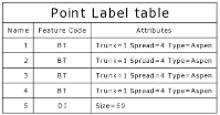
Example when check box is checked:
- When you are done, click OK to save the new label table style.
The new style is available for selection when you create a label table.
To edit or delete an existing label table style:
- Select Label Table Style Manager in Drafting > Tables and select the tab for the type of label table style you want to edit or delete in the Label Table Style Manger dialog.
- Select the style you want to edit or delete in the Label Table Styles list.
- To delete the selected style, click the Delete button.
The deleted style is no longer available to select to apply to a line, point, or polygon. In addition, any label tables in the project that use the deleted style are converted to the Standard style.
- To edit the selected style, make changes as necessary on the Items, Border, and/or Text tab.
See the previous procedure for additional instructions. Any changes you make on these tabs are automatically applied to any existing instances of the style in the project.
- When you are done, click OK to save the changes.
