Workflow for Topsoil Stripping Along a Corridor
The goal in this workflow is to address the typical takeoff needs of an earthmoving contractor who is responsible for topsoil removal along a corridor. The process involves starting with an original ground (OG) surface model and in-site material, creating a topsoil material that is unsuitable for respread, and then defining the top strata layer along the corridor as having that topsoil material.
Note: Your tasks may vary from these typical steps, so feel free to use a different order or skip steps.
|
Steps |
Help by Command |
|
|
1. |
Import any data you need to do a corridor takeoff, such as the alignment, original ground surface, stripping surface, and/or linework outlining topsoil areas to strip. |
|
|
2. |
Create the topsoil material that you intend to strip in the Earthen (Mass Earthworks) material category. Give the material a nature of Topsoil. In Topsoil Properties for the material, identify material as having a grade of Unusable. Also create an in-situ material for the site soil (use a different material color). |
|
|
3. |
Define strata for the corridor:
|
|
|
4. |
Create a corridor from a horizontal alignment. Specify the OG surface, native materials, and OG and strata surfaces as reference surfaces. |
|
|
5. |
Create and insert one or more cross-section templates as necessary into the corridor. |
|
|
6. |
Add template instructions to specify tie slopes for the stripping. |
|
|
7. |
Use the slider at the bottom of the Corridor Template Editor to investigate the topsoil stripping along the corridor. See Notes below. |
|
|
8. |
Run a report to determine the volumes of cut and fill materials needed along specific portions of the corridor. |
|
Notes:
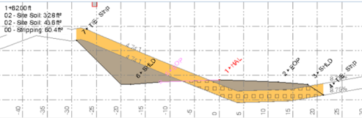
- The stripping and site soil areas will be shown in different colors.
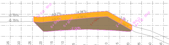
Figure: Topsoil stripping along a corridor (cross-section view)
- The tie slopes will tie vertically to the OG surface. If you want the tie slopes to continue at the same slope to tie to the OG surface, you can add a second side slope instruction to tie to the OG at the same cut and fill slopes; at the toe of the fill slope. This will also generate a layback required for excavations of the stripping material. If you want the vertical elements in the Finished Surface model, then you will have to add a side slope instruction with a vertical (up or down) tie and a 0 cut ditch width. You can use the words Up and Down in the Slope ratio field.
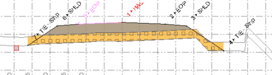
- In fill areas, you will see something like the figure below. The orange stripping layer is quantified and also patterned with squares, indicating that the stripped area is also computed as a fill area in this case.
- Where you have both cut and fill conditions at the same station, it will appear something like the figure below. The text at the top left shows both the cut and fill area for in-site soil. The naming of the native cut and fill materials dictates what is shown here and in reports.