Work with Block Feature Definitions
You can create a unique feature definition for each type of feature a user may need to record in the field. There are four types of feature definitions available: point, line, polygon , and block.
A block feature is made up of a single block, which is a collection of individual CAD objects (sometimes containing nested blocks) that are grouped together into a single larger object to make selecting and moving the related objects easier and more consistent. For example, a block might be used to represent an automobile or some other recognizable feature.  More about block features...
To create a block feature definition:
Note: If you want to create a new feature definition that will share properties with an existing definition, you can, as an alternative to the instructions presented here, copy the existing definition and then modify the copy as necessary (including assigning it to a different category) using the instructions below. See Create a New Feature Definition Based on an Existing Definition for additional information.
- In the Project Explorer, right-click the node representing the feature definition category to which you want to assign the new block feature definition and select New Block Feature Definition.
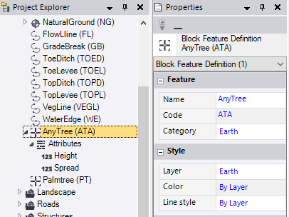
A new Block Feature Definition node displays nested beneath the selected Category node in the Project Explorer. In addition, the Block Feature Definition Properties pane displays.
- Complete the fields as described in "Properties" below.
- To assign an attribute to the new block feature definition, see Work with Feature Definition Attributes.
To edit or delete a block feature definition:
In the Project Explorer, right-click the node for the block feature definition you want to edit or delete and do either of the following:
- Select Properties to display the Block Feature Definition Properties pane. Then make any necessary edits as described in "Properties" below. Your changes are saved automatically.
- Select Delete.
Note: If you delete a feature definition that has been assigned to a point in your project and then reprocess the feature codes, the deleted definition will no longer be recognized and will be reported as "Unknown" in the Feature Code Processing Report.
Properties:
|
Feature |
|
| Name |
Enter a unique name for the block feature definition. Duplicate feature definition names cannot be used in the same Feature Definition (.fxl) file. |
| Code |
Enter a unique code for the block feature definition. Typically, the code is an abbreviation for the feature definition name that can be easily assigned to a point in the field. Duplicate feature definition codes cannot be included in the same Feature Library for the same feature definition type. |
| Category |
Select the category to which you want to assign the feature definition. Categories are used to organize feature definitions into sets of similar definitions. For instructions on creating categories, see Work with Feature Definition Categories. |
|
Style |
|
| Layer |
Select an existing layer on which the block feature will display. Or, select <<New Layer>> to create a new layer for the feature. For additional instructions, see Manage Layers. |
| Color |
Select the color to use for the block feature. Or, select By Layer to use the color specified for the layer on which the block feature displays. |
| Line style |
Select the line style to use for the block feature. Or, optionally:
|
|
Point |
|
| Include in surface |
Select Yes to specify that a point to which this feature definition is assigned, along with the resulting block feature, can be included as a member in a surface. Note: If multiple features are assigned to a point, only the first feature code displayed in the Feature code field in point's Properties pane (the "primary feature") will use this setting to determine if the point can be included as a member in a surface. |
| Point label style |
Optionally, select a predefined point label style that specifies the following for each point to which this feature definition is assigned:
See Create and Edit Label Styles for more information. |
| Point layer |
Select an existing layer on which each point to which this feature definition is assigned will display. Or, select <<New Layer>> > to create a new layer for the point. For additional instructions, see Manage Layer.. |
|
Block |
|
| Block |
Select the predefined block you want to use to create the new feature definition. For additional information, see Work with Blocks and Work with Block Control Codes. |
| Insertion |
Select one of the following block insertion options:
Note: If you select to use a block insertion method that uses more than one insertion point, the rotation value resulting from the location of the second insertion point will be added to any rotation value you might enter in the Rotation field; scale values will be multiplied by any values you might enter in the Scale X and Scale Y fields. |
| Rotation |
Optionally, enter a value for the degrees of rotation for the block. (See Insertion note above.) |
| Scale X |
Optionally, select a scaling value on the X axis. (See Insertion note above.) |
| Scale Y |
Optionally, select a scaling value on the Y axis. (See Insertion note above.) |
| Scale Z |
Optionally, select a scaling value on the Z axis. |
