Extract Lane Line Marking Features from a Point Cloud
Use the Extract Line Features command to extract linestrings from single solid, double solid, and dashed lane marking line features displayed in a point cloud or Mobile Mapping run that includes a 360-degree images. The extraction process results in the creation of a linestring and, optionally, line node points based on a contiguous stretch of solid or dashed road marking lines.
Prerequisites:
See the Subscription Plans page. For a license matrix by command, see the License page in the TBC Community. Also see View and manage licensed features.
To extract lane line marking features:
- Select Extract Line Feature in Point Clouds > Extraction to display the Extract Line Feature command pane.
- In the Extraction type drop-down list, select Lane Line Markings.
The graphic views change to display point clouds in gray-scale (with no intensity specified), if they are not already.
- Click the appropriate option for extracting lane line features:
- Semi-automated - This option enables you to manually select the lane lines to be automatically extracted from a point cloud (no Mobile Mapping run required). If TBC encounters a problem during the extraction process due to line feature irregularities or sparse scan points, you can, with the aid of several helpful tools, make manual point selections to continue the extraction process.
If you select the Semi-automated option,  click here to continue.
Semi-automated line extraction:
- If you have not already done so, click the Semi-automated option.
- Optionally, click the Line Settings drop-down group box and enter a Name and/or assign a Layer, Line style, and Color to the extracted linestring.
- In the Extraction group box, select the Lane line type you want to extract:
Solid single or Solid double
If you select Solid single or Solid double:
- Click in the Line point field. Then, in the 3D View or Plan View, do either of the following:
- Solid single - Click directly on the solid single lane line marking you want to extract.
- Solid double - Click directly between the two lane line markings you want to extract.
Notes:
- If you click a location that is not on or near a lane line marking, a red extraction icon displays. Try again.
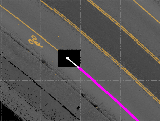
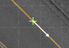
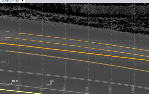
- For best results, it is recommended that you select a point on the lane line that is not too close to either end and is on a straight length of road rather than on a curve. However, if you do pick on the end of a line, the extraction process automatically specifies that the initial direction of the extraction process be away from the end of the line (as indicated by the white arrow), where it might not find adequate points to continue. (If you pick anywhere else on the line, the initial direction of the extraction process is always to the right.)
The default gray-scale Intensity threshold, which is specified in Advanced Settings (see step b below), is automatically applied to the graphic views.
A green extraction icon displays where you clicked on the line, along with a white arrow indicating the direction of the initial point search for the automatic extraction process.
Note: Optionally, you can click the Switch Direction arrow to start the initial point search in the opposite direction along the line.
The extraction process is based on point cloud intensity and requires that each lane line selected for extraction be as clearly delineated as possible. A gray-scale intensity threshold that is too low or too high makes it difficult for the extraction to perform, resulting in the process stopping and the need for manual intervention to continue. The default intensity threshold setting typically works well.
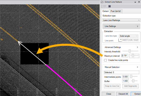
- Optionally, in the Advanced Settings group box, use the Intensity threshold slider control to further delineate the scan points for the lane line marking as necessary.
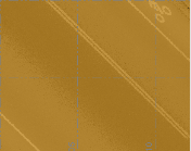
Low:
High:
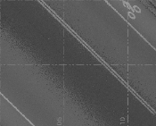
Optimal:
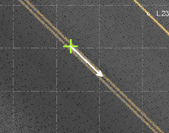
- Optionally, in the Advanced Settings group box, enter or use the slider control to change the Maximum interval distance, which determines the length of each road marking line segment to be searched and extracted at a time, as indicated by the length of the white arrow.
The white arrow lengthens or shortens accordingly in the graphic views to indicate the specified distance.
For fastest processing, you might define an interval that is as long as possible (less line segments to extract). This can work well on long stretches of straight lane line markings with minimal curves and adequate scan points within the selected interval distance. However, you must consider how best to handle situations of curving road marking lines, sparse scan points, and so on to minimize how often the extraction process stops, requiring your input to help it continue.
Note: You are encouraged to experiment with different Maximum interval values to achieve optimal extraction results.
You can adjust the Maximum interval distance either before you begin the extraction process or if you are restarting the process when it stops due to line marking scan points not being being found.
- Optionally, select to create a new point at the start of each line segment, and the end of the final segment, as follows:
- In the Advanced Settings group box, check the Create line node points check box.
- Optionally, change the default Staring Point ID from the displayed default.
- Optionally, change the default Layer selected for the new points.
- Optionally, enter or select a Feature code to assign to each new point.
The line segment length is determine by the specified Maximum interval.
Dashed
If you select Dashed:
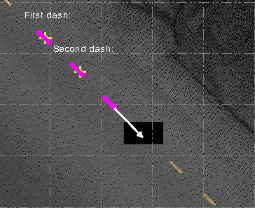
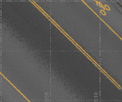
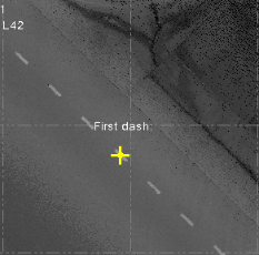
- Click in the First dash field. Then, in the 3D View or Plan View, click in the middle of a dashed line in the Plan View.
Notes:
- If you click a location that is not on or near a lane line marking, a red extraction icon displays. Try again.
- For best results, it is recommended that you select a dash on the lane line that is not too close to either end and is on a straight length of road rather than on a curve.
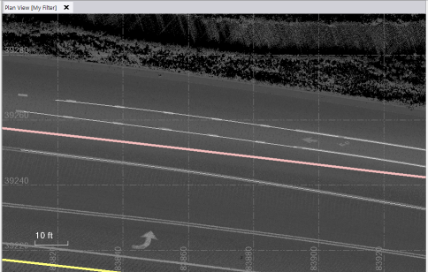
A yellow extraction icon displays on the dash where you clicked
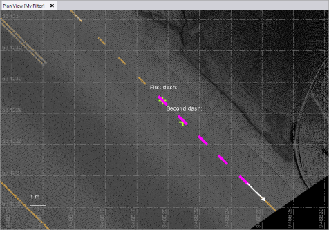
- Click in the Second dash field and then click in the middle of the next dashed line in sequence as shown below.
The default gray-scale Intensity threshold, which is specified in Advanced Settings (see step c below), is automatically applied to the graphic views.
The green extraction icons turn from yellow to green to verify both selections are valid and you can begin the extraction. Two white arrows indicate the direction of the initial point search for the automatic extraction process.
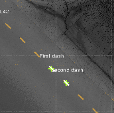
Note: If you had selected a second dash to the left of the first dash (in this example), the white arrow would be reversed and the automatic extraction process would start in the opposite direction.
- Optionally, in the Advanced Settings group box, use the Intensity threshold slider control to further delineate the scan points for the lane line marking as necessary.
Low:
High:
Optimal:
- Optionally, select to create a new point at the start and end of each line dash, as follows:
- In the Advanced Settings group box, check the Create line node points check box.
- Optionally, change the default Staring Point ID from the displayed default.
- Optionally, change the default Layer selected for the new points.
- Optionally, enter or select a Feature code to assign to each new point.
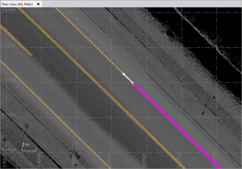
- To begin the automatic extraction process, click the Extract button or press the Enter key.
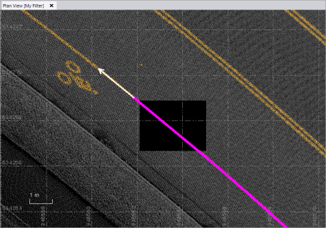
A progress bar displays at the bottom of the window. Each extracted segment is displayed in magenta as it is extracted. The extraction process is performed in one direction until it reaches the end of the line (no more road marking scan points are found).
Example of Solid single line marking extracted in one direction:
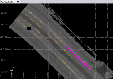
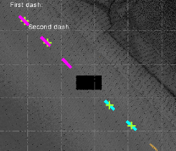
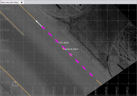
Example of Dashed line marking extracted in one direction:
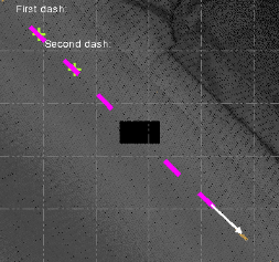
- To continue the extraction in the opposite direction from the line selection location:
- Click the Switch Direction button.
A white arrow displays at the extraction start point, pointing in the opposite direction.
- Click the Extract button.
The extraction process continues from the start point until it reaches the opposite end of the selected road line marking.
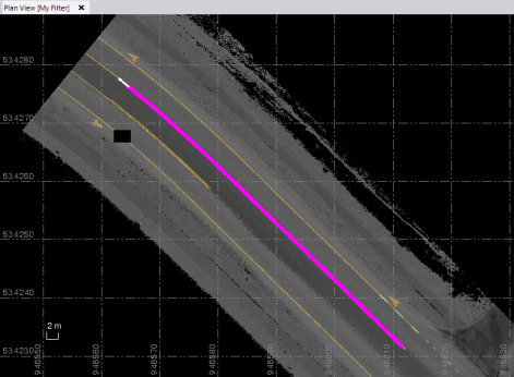
Example of Solid double line marking extracted in both directions:
Example of Dashed line marking extracted in both directions:
Note that during the extraction process for dashed lines, a dashed linestring style is automatically created by default and applied to the linestring that matches the start/end of each extracted dash, so the linestring and the extracted dashed line match.
You can click the Stop button at any time to stop the extraction process (for example, you don't want to capture the entire lane line marking). If the extraction process is stopped, click the Discard All Button to clear the current extraction results and start over.
- Do one of the following:
- If your linestring was extracted successfully, proceed directly to step 9.
- If the extraction process stopped before completion in either direction, continue with step 8.
- Zoom in on the Plan View or 3D View to see where the problem is occurring, and do one or more of the following as applicable to continue with the extraction process:
If segments were extracted in error, you can click the Undo button as necessary to delete previously extracted segments. Then proceed using one of the following options in this step.
- Once extraction is complete, do either of the following:
- Click the Create Line or Create Line and Point button to completed the extraction process and save the extracted linestring and points (if applicable) in your project without making any additional changes.
- Select the Post QA/QC tab and, optionally, select one of the Smooth Line Options (not applicable for dashed lines) and/or change any of the Line Settings for the extracted linestring. Then, click the Create Line button to complete the extraction process and save the extracted linestring and points (if applicable) in the project.
You can select the new linestring in the 3D View or Plan View and edit if necessary.
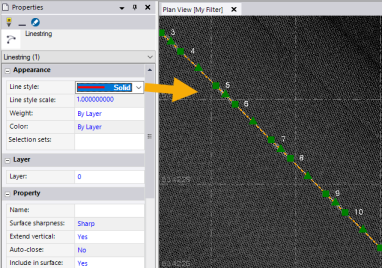
Example of a linestring and node points extracted from a solid single lane line:
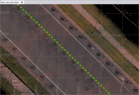
Example of a linestring (without node points) extracted from a solid double lane line:
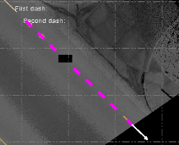
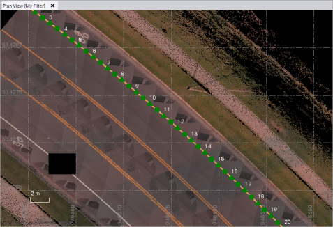
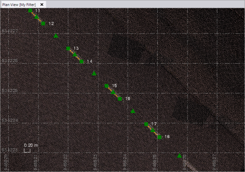
Example of a linestring and node points extracted from a dashed lane line:
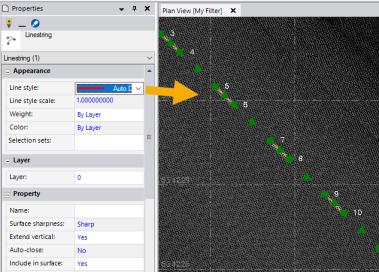
In the case of dashed lines, you can use the Properties pane to toggle between viewing the linestring using the Auto-Dash linestring style that was applied automatically during extraction or the Solid linestring style.
Note: With the exception of a few scenarios, you can export the extracted dashed linestring as a 2D polyline that will display correctly in AutoCAD or other CAD systems. If you export it as a 3D linestring, it will display as a solid line.
- Automatic (Mobile Mapping) - This option enables you to automatically extract linestrings from pavement lane lines in images captured with a Trimble Mobile Mapping system that includes a 360-degree camera and laser scanner. Working with a pre-classified Ground point cloud region (see Extract Classified Point Cloud Regions), a deep learning model is used to detect lines on each image frame and automatically map them to the point cloud to create 3D linestrings.
If you select the Automatic (Mobile Mapping) option, click here to continue.
Automatic (Mobile Mapping) lane line extraction:
- If you have not already done so, click the Automatic (Mobile Mapping) option.
- If your project does not already include a pre-classified Ground point cloud region, create one now (see Extract Classified Point Cloud Regions for instructions).
- Optionally, click the Line Settings drop-down group box and enter a Name and/or assign a Layer, Line style, and Color to the extracted linestrings.
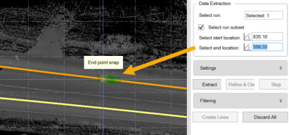
- In the Data Extraction group box, do the following:
- Click in the Select run field and then, in the Project Explorer or a graphic view, select the Mobile Mapping run/trajectory containing lane lines from which you want to extract corresponding line strings.
- Optionally, check the Select run subset check box to extract linestrings from just a portion of the Mobile Mapping run. Then, click in each of the Select location fields and click on the trajectory to specify the start and end points for the portion of the run to be included in the extraction process. (It does not matter in which direction you select the points.)
- In the Settings drop-down list, check any of the following options:
- No refinement - This option does not refine the extracted linestring. This option has a faster processing time.
- Refine - This option automatically applies rectification to the Mobile Mapping images and centers the extracted linestring on the lane line for a more refined, precise linestring. Note that refinement will increase processing time by approximately 50%.
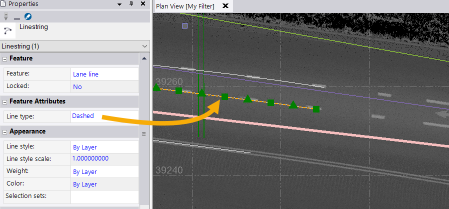
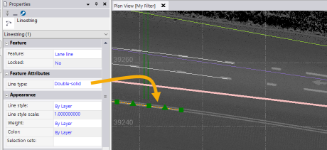
- Refine & Classify - This option automatically identifies the line type feature attribute for each extracted linestring (for example, solid, double solid, or dashed) and displays it in the line's Properties pane. It also splits extracted lane lines as they change type (for example, from dashed to solid, or solid to double solid) and classifies each linestring accordingly.
The following examples show linestrings that were extracted and saved in the project, along with their Feature Attribute properties.
- Create line node points - This option automatically creates a point at each node in the extracted linestrings.
The next example shows linestrings that were extracted and saved in the project with a point located at each node.
- To begin the automatic extraction process, different options are available, depending on which Refinement Setting you selected. The options include:
- Extract
- Refine
- Refine & Classify
- Extract & Refine
- Extract, Refine, & Classify
You can click the Stop button at any time to stop the extraction process. If the extraction process is stopped or if you want to begin the process again, click the Discard All Button to clear the current extraction results and start over.
A progress bar displays in the TBC Status Bar at the bottom of the <ProduceAbbrev> window. Each extracted segment is displayed in magenta as it is extracted. The extraction process is performed in each direction until it reaches the ends of the lines (no more road marking scan points are found).
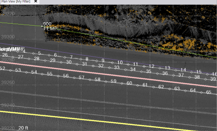
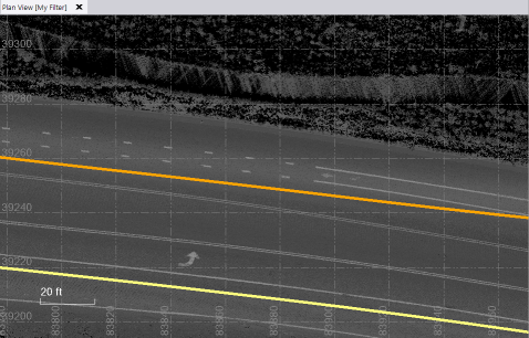
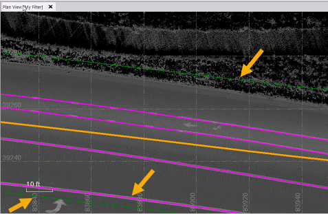
The following example shows the short stretch of roadway from which linestrings will be extracted based on the selected Mobile Mapping run trajectory (orange line) and selected run subset. Note that dashed, solid, and double-solid line types are included in this example.
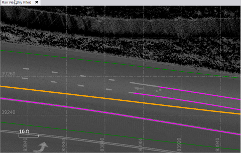
After extraction, the extracted linestrings are colored magenta. They are not yet saved in the project.
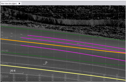
This example shows the Classify option selected, which results in linestrings that are split based on the lane line type change from solid to dashed.

- Optionally, expand the Filtering drop-down box and make changes as necessary:
Limit extraction by trajectory - Use this slider control (or enter a distance value) to narrow or widen the area on either side of the selected run trajectory from which lane lines will be extracted. This distance is represented by two green filter lines in the graphic view. Any lane lines outside these filter lines are excluded from the extraction.
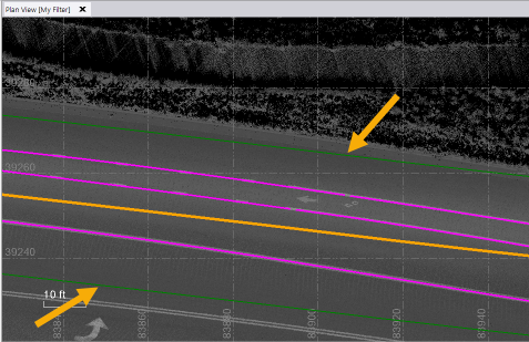
In the following example, the distance from the trajectory was widened to include an additional double solid linestring.
Remove short lane lines - Use this slider control (or enter a distance value) to specify the minimum length a lane line must be to be included in the extraction.
In this next example, the minimum lane line length was increased to the point that the dashed line is no longer being extracted due to the length of its individual dashes.
- Do either of the following:
- If you are certain you do not have to make changes on the Post QA/QC tab, click the Create Lines button to save the extracted linestrings in the project.
- If you want to view or make changes on the Post QA/QC tab, select it and do any of the following as applicable:
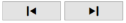
- Click the backward and forward arrows at the top of the tab as necessary to select any extracted linestring. Then you can choose any of the following options:
- Ignore - Color the linestring red and do not save it in the project.
- Normal - Save the extracted linestring in the project.
- Mark - Color the linestring white to flag it for additional consideration.
You can also smooth the selected linestring or change its settings as described below.
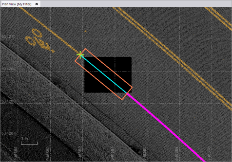
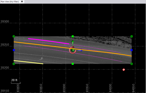
- Click the cube button to create a window in the Plan View that allows you to view the extracted linestrings from different perspectives to more carefully examine them.

- Select one of the Smooth Line Options for the selected linestring (not applicable for dashed lines). Or, click the Apply to All button to apply the setting to all of the extracted lines.
- Enter Line Settings for the selected linestring, if they are different than the Line Settings you specified on the Extract tab. Repeat for other linestrings if applicable.
- If you did not already click the Create Lines button on the Extract tab, click the Add All button on the Post QA/QC tab to complete the extraction process by saving the extracted linestrings in the project.
- Optionally, edit any of the newly created linestrings as necessary. See Edit a Linestring's Horizontal Segments for instructions.
Related topics
Create and Edit a Linestring
Extract Line Features from a Point Cloud
Extract Overhead Line Features from a Point Cloud
Extract Curb and Gutter Line Features from a Point Cloud
Extract Point Features from a Point Cloud
Create and Edit a Linestring