Run a Tunnel Set Outs As-Built Report
Generate a customizable Microsoft® Word-based report that compares the location of as-built tunnel set out points with their associated set out reference points in the tunnel design. This report can be used for quality control and verification on surveyed vs. constructed positions of rock bolts, anchors, pipe umbrellas, and more.
Prerequisites:
- Licensed module. See the Subscription Plans page. For a license matrix by command, see the License page in the TBC Community. Also see View and manage licensed features.
To set Tunnel Set Outs As-Built Report options:
- Select Report Options in the Quick Access Toolbar to display the Report Options command pane.
- In the Reports list, select Tunnel Set Outs As-Built Report.
- Edit Settings options as necessary.
You can click each option to see its description displayed below the Settings box.
To run a Tunnel Set Outs As-Built Report:
- Select Tunnel Set Outs As-Built Report in Tunnels > Reports to display the Tunnel Set Outs As-Built Report command pane.
- In the Report template drop-down list, select the default Word report template Tunnel Set Outs Report, or select a customized version of the report if available.
Note: To create a customized version of the provided default template Tunnel Set Outs As-Built Report (for example, add available unused fields to the report),see "Create and Edit Customized Report Templates".
- Select the Tunnel and Tunnel shape you want to use in the comparison.
Only set out reference points assigned to the selected shape will be included in the report.
- In the Target set out types list, ensure the set out point types you want to include in the report are checked.
The As-built set out points table includes the stations to which set out points are assigned, and the number assigned to each.
- Optionally, select a different Begin station and/or End station to determine which station's set out points will be included in the report.
The defaults are the begin and end stations for the entire tunnel.
- Optionally, change the distance value displayed in the Station tolerance, Horizontal offset tolerance, and/or Vertical offset tolerance fields (the default value for each is 0.1 m).
If the location of an as-built set out point in relation to its corresponding station and design set out point exceeds any of these tolerances:
- The as-built point is displayed in the report's cross-section view in the tolerance-exceeded color specified.
- The exceeded tolerance value is displayed in the report's "Design Points and Staked Points" table in the tolerance-exceeded color specified.
- Optionally, change the distance value displayed in the Design and as-built matching tolerance field (the default value is 1.0 m).
Any as-built set out point located farther than this distance from its corresponding design set out point will not be included in the report.
- Optionally, change the default colors used to identify whether as-built set out points exceed or are within the specified tolerances.
- In the Image Scaling group box, select the most appropriate option:
- Use the same scale for all stations - All cross-sections displayed in the report will be drawn to the same scale.
- Best fit scale per station - All cross-sections displayed in the report will be drawn to the maximum size allowed in the page layout regardless of the scale.
- Click the Apply button.
The report opens in MS Word.
Each station included in the selected station range is represented in the report by two or more pages that include the following elements:
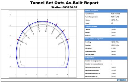
- A heading showing the station number.
- A cross-section view of the tunnel showing design and as-built set out points along the tunnel shape at the specified station. As-built set out points that exceed specified tolerances are displayed in the specified tolerance-exceeded color.
For the report, design set out points of each type are numbered, starting at 1, from the bottom left side of the tunnel alignment around the tunnel shape in a clockwise direction. The point number includes a code indicating its set out type (radial, horizontal, vertical, or blast hole). The report compares only set out points of the same type.
In the example above, the blue tunnel shape line represents the specified tunnel shape on which set out points are being compared. The gray tunnel shape lines represent the other tunnel shapes defined for the tunnel, which are not included in this report.
- A table showing general information about the report: tunnel information, tolerance settings, cross-section information, and general computation results.
- The "Design Points and Stake Points" table, which compares each as-built set out point to its associated design set out point and station, and lists all offset and delta offset values. Delta offset values that exceed specified tolerances are displayed in the specified tolerance-exceeded color, as in the cross-section view.
- The "Point-to-Point Comparison" table, which compares distances between two consecutive design set out points of the same type (starting with point 1) and two corresponding consecutive as-built set out points.
- Optionally, save the Word file with a new name to the location of your choice.
