Create Composite Geometry
Use the Create Composite Geometry command to combine simpler geometry objects, such as lines and/or polygons, into a single multipart geometric object used to represent complex spatial features, including objects with "holes" through them, such as bridges and archways.
You can specify to include composite geometry when exchanging data with a GIS data source using the Read Features from GIScommand or the Write Features to GIS command.
Preequisites:
- Licensed module. See the Subscription Plans page. For a license matrix by command, see the License page in the TBC Community. Also see View and manage licensed features.
- Existing lines or polygons you want to combine in the composite geometry.
To create composite geometry:
- Select Composite Geometry in CAD > Edit to display the Create Composite Geometry command pane.
- In the Composite type drop-down list, select whether you want to create a Composite polygon or Composite polyline.
- Optionally, in the Color drop-down list, select a color to apply to composite polylines or as a fill color for composite polygons.
- Optionally, in the Layer drop-dow list, select a different layer on which to display the composite geometry.
- Click in the Elements to add to composite field and then, in the Plan View, draw a selection box, or use Shift + click or Ctrl + click, to select two or more lines or polygons (depending on your selection in the Composite type drop-down list) to add to the new composite geometry.
Optionally, click the Options button for additional selection options.
If necessary, click the Remove button to clear your selection.
Note: If you are creating multiple composite polylines or polygons, you can select the same polyline to be a member of each, as in the case of a parcel boundary line that belongs to a parcel on either side of it.
- Click the Add button.
Your selections are displayed on the Elements added to composite table.
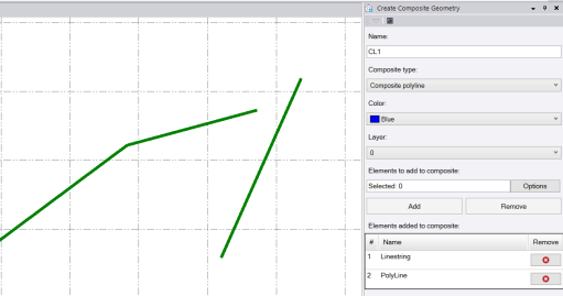
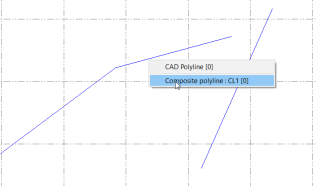
In the following example, a linestring and a polyline were selected to be members of a new composite polyline.
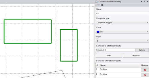
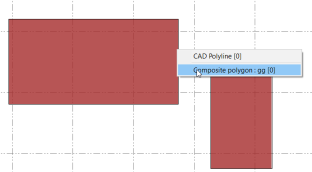
In the next example, two polygons were selected to be members of a new composite polygon.
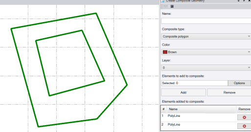
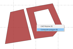
In this last example, two polygons (one contained within the other) were selected to be members of a new composite polygon.
Optionally, click any row in the table to highlight the referenced geometry in the Plan View.
If necessary, click the Remove button to remove any elements from the table.
- Click OK to create the new composite geometry.
The new composite polyline or polygon is appropriately labeled and displayed in the Plan View. Note that each element referenced in the composite geometry is still selectable and editable. And if you do edit a referenced element, the composite geometry is changed accordingly.
Following are a few examples.
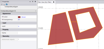
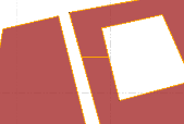
When a selected polygon is contained within another polygon in the composite geometry, the smaller polygon creates a "hole" within the larger polygon. A connecting line is automatically drawn in the Plan View linking the two polygons.
To view the properties of a composite geometry object, left-click to select it in the Plan View, right-click, and select Properties to display its Properties pane. Here, you can change the color, layer, and/or name of the object.