Offset a Line
Use the Offset Line command to create a new linestring offset at a specified distance from an existing line. The line from which you are offsetting can be either 2D (such as a boundary, polyline, circle, or an alignment without a vertical alignment (VAL)) or 3D (such as a 3d linestring or an alignment with a VAL). In addition, the offset can be horizontal, vertical, or both. Line segments offset from spirals and smoothed segments are chorded.
By default, the command creates a copy of the entire line, but you can choose to offset only a portion of a line by specifying by a begin and end station along the line (the offset segment cannot start/end beyond the ends of the line).
Prerequisites:
- See the Subscription Plans page. For a license matrix by command, see the License page in the TBC Community. Also see View and manage licensed features.
- Reference line from which to offset
To access the command:
- Select the linestring or polyline you want to offset from and do one of the following:
- Select Offset Line in CAD > Edit.
- Right-click and select Offset Line from the context menu.
To create a line offset from an existing line:
- If you want to uniquely identify the new offset line, type a name in the Name box.
- Select a layer on which to place the offset line in the Layer list.
- Confirm the Line to offset from, or pick a line in a graphic view or the Selection Explorer. Alternately, you can click Options and choose a selection method from the context menu.
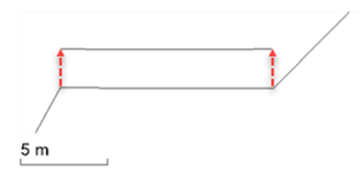
- In the Offset distance box, specify the distance (perpendicular to the original line) at which you want to create the offset line.
Note: If desired, click the
 icon to toggle the auto-advance mode on. When the icon looks like this
  , the offset value you entered will be held and this box will be skipped when creating additional offset lines.
Tip: You can toggle the Auto-advance mode on/off by pressing [Control] + [.] (period or decimal point). - In the Side to offset list, click to the side of the selected line in the view or select a side on which to create the offset line.
Note: The side is based on the direction of the line, which can be also determined using the Explore Object command.
- If needed, specify a vertical distance to offset the line from the original line in the Vertical offset box. Otherwise, the segments of offset line will have the same elevations as the corresponding segments of the selected line.
Note: You can enter an elevation for the offset line using a vertical angle (and distance) from the reference line. The vertical angle can be specified in the elevation control in a variety of ways, including: nadir angle, horizon angle, percent, and ratio. In addition to the vertical angle, the elevation control supports basic math operations, +-*/, e.g., you can specify "%5 + 3" which means 5% of the offset plus 3, with an offset of 100 the resulting elevation would be 8.
Note: if needed, click the icon to hold the present vertical offset value and skip this box when creating additional offset lines. - To offset only a portion or segment of the line, check the Offset a segment box, and specify the Starting point and Ending point of the segment to offset.
Tip: How the offset segment is created can depend on how the line was drawn (direction/order of nodes), and whether the line creates a closed shape. If, for instance, the segment you specify to offset spans the start/end points of a closed line, you may get unexpected results. To better control the segment that gets offset, you may need to use the Break Line and Join Lines commands to create just the segment you want to offset.
- Click Apply to create the offset line. The offset line/segment is created next to the originally selected line; it is also selected as the next line from which to offset.
Tip: To create a series of lines offset at the same interval, simply click Apply repeatedly after specifying the offset distances and side.
Tip: If you toggle the auto-advance mode on for both the offset distance and vertical offset, you can quickly offset many lines by repeatedly picking the line to offset and the side.
Scenarios:
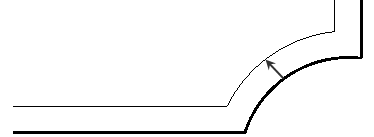
- If the reference line contains acute angles, the resulting offset line may be malformed.
- When you offset a segment, the offset portion is calculated independent of the geometry of adjoining segments; the begin and end segment values are based only on the start and end points you specify on the original line. Internally, the program creates a copy of the line being offset and trims that line to the specified points before the offset is made.
Tip: When you offset a line with a vertical curve, you will lose the curve and get a series of points, so go to Project Settings > Computations > Surface > Breakline approximation and change the Vertical tolerance as needed.
Dependencies:
- None; once created, the offset line is independent from the reference line.
