Create a Cut/Fill Map
Use the Create Cut/Fill Map command to create a map that indicates areas on a surface to cut and fill (based on a specified tolerance) to achieve a design. The cut and fill areas can be indicated by shading and/or a grid of values labeling the elevation differences between two surfaces, such as an original and a design surface. On the grid, measurements are color-coded to indicate where earth needs to be cut or filled. The map will dynamically update in response to edits to the surfaces on which it is based.
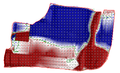
A cut/fill map is not a surface, but rather a difference model (isochore). Difference models are created by both this command and the Earthwork Report command.
You can modify the colors displayed in the map, and you can also load color map files (.tcf) with predefined palettes. See Edit Color Mapping for a Surface or Difference Model for details.
Prerequisites:
- License; See the Subscription Plans page. For a license matrix by command, see the License page in the TBC Community. Also see View and manage licensed features.
- Two surfaces (usually an original and a design surface)
To access the command:
- Select Create Cut/Fill Map in Surfaces > Edit.
To create a cut/fill map or grid:
- In the Name box, type a unique identifier for the map as you want it to appear in the in the Selection Explorer and Properties pane.
- Select a surface in the Initial list.
You can select a surface with any classification, but the initial surface should reflect the state of topography before the surface you select as the final surface.
Note: If you select a projected surface as the Initial surface, you must select a projected surface using the same UCS (user coordinate system) for the final surface (see next step).
- Select a surface in the Final list.
Again, you can select a surface with any classification, but the final surface should reflect the state of topography after the surface you selected as the initial surface.
- For Map Features, check one or both boxes:
- Shade map - Select this to display cut and fill areas in graduated colors based on the current color mapping. If you choose to uncheck Label grid (below), skip to step 10.
- Label grid - Select this to display a grid of values showing cut and fill depths and specific locations on the difference model. Then specify the options in steps 5 through 9 below.
- Select the layer on which you want the grid to reside in the Layer box, or select <<New Layer>> to create a new layer for the grid.
- Select a style that controls the text font, font style, justification, and size for the grid annotations in the Text style box, or select <<New style>> to define a new text style.
- In the Grid spacing box, type a value for the uniform interval at which the grid lines or tick marks for the measurements will be spaced.
- Select an option for how the location of each measurement will be denoted in the Grid style box.
- Select the number of decimals to use in the grid's measurements in the Decimal precision list.
- Check the Label Surface Elevations check box if you want to display elevation values on the map.
Note: This option is not available if you are creating a cut/fill map from projected surfaces.
- Click . The cut/fill grid is created and appears in graphic views and the Project Explorer. Additional properties, such as the grid's insertion point and rotation, and cut, fill, and zero colors, can be set in the Properties pane.
Note: When you explode a cut/fill map, CAD points are created at the tick mark locations.
Important cut/fill map properties:
In the Properties pane [F11] for a selected cut/fill map, you can:
- Set Drape surface to Yes to display the cut/fill map shading and labels at the elevation and in the shape of the surface selected as Final in this command.
- Choose to display elevations for the surfaces selected as Initial and Final at the tick marks on the map.
- Use these values to generate a specific cut or fill based on a target balance value:
- Approximate balance amount - Vertical distance to move either surface to balance the cut/fill volumes.
- Approximate volume delta per 0.1 unit - Approximate volumetric change if either surface is raised or lowered 0.1 of the project distance unit.
For example, if you know what is required to balance a site, but you need a 1000 yd export, use the balance amount to determine the design elevation adjustment you need to make to get to the export overage volume. The approximate volume delta is also shown in the Earthwork Summary Report as “Change Per 0.1”.
Options:
- See Cut/Fill Map Options.
Dependencies:
- The map is a dependent object; it will dynamically update in response to edits made to the related surface.
