Inspection Tool
The  Inspection Tool includes the Cut & Fill inspection process, which is used in construction and civil engineering to determine the amount of material that needs to be excavated (Cut) and the amount that needs to be added (Fill) to achieve a desired terrain or surface level.
The Inspection Tool requires a paid licensing module for use. See Module Licenses.
The process begins with collecting detailed data on the site using laser scanners.
Before running a cut and fill inspection on the collected data, ensure that the data has been registered and refined. If not, the application will display a warning and prompt to complete this step.
During a cut and fill inspection, you can continue collecting data. The data will be downloaded and automatically registered, but it will not be displayed and therefore not used in the current inspection. If the registration fails, the data can be manually registered, but only after exiting the inspection process.
Display only the data you want to inspect and hide any data you wish to exclude from the inspection process.
-
Tap
Inspection Tool. The Inspection panel opens. -
Tap Create New to proceed.
-
Define the settings for an inspection.
Name: Define a name or use the default name (Inspection N).
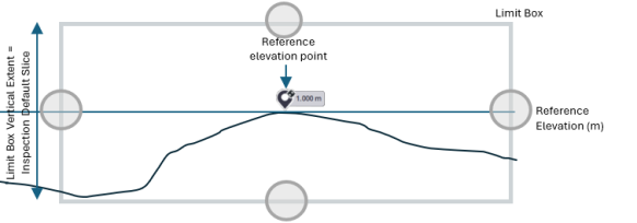
Reference Elevation: This is the baseline elevation used as a point of comparison for the cut and fill operations. It represents the desired final surface level that the site should achieve after the earth-moving process. All calculations for the cut and fill values are based on this reference elevation.
Select a point from the point cloud with the
 2D/3D Picking button or using the
  Laser Pointer. This point will be your reference elevation point. Once the point is selected, set an elevation value for it.
 You can also pick an annotation (or a precision point) to set it as a reference elevation point using the
2D/3D Picking button.The default reference elevation value is 0 meters. In order to avoid negative values, the minimum value is 0 meters, and the maximum value is infinite.
To be able to pick an elevation with the
Laser Pointer, you need to be connected to your scanner and have already acquired a scan.You can use the
 Magnify tool to zoom in on a specific area to accurately select a reference elevation point. See Magnify.
Once the reference elevation has been defined:
-
An
 annotation pin with the set value is displayed over the point (selected with the 2D/3D Picking button).
 -
A
 precision point pin with the set value is displayed over the point (selected with the Laser Pointer).
 -
A Limit Box with manipulators (handles) is displayed centered at the selected point. The height of the box is by default 50 milliliters by default. Define an area for inspection. See Limit Box.
The Limit Box Vertical Extent value of the limit box is updated and synchronized with the value of the Inspection Default Slice Size after selecting a Reference Elevation point. Changing the Offset has no influence.
-
The rendering switches to
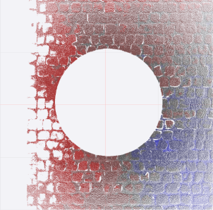
 Inspection Preview to display a visual representation of the floor surface using the Color Palette (red, gray, and blue) to indicate areas of different elevations:
 Red, above the reference elevation.
Gray, at the reference elevation (including tolerances).
Blue, below the reference elevation.
Offset: Is the vertical distance used to adjust the reference elevation either upwards or downwards. It allows you to modify the reference elevation to achieve the desired Surface Elevation. If you do not want to apply an offset, keep it at zero, and calculations will use the original reference elevation. If you apply an offset, calculations will use the updated reference elevation (Surface Elevation).
-
 Surface above reference is to add an offset to the original reference elevation, moving the reference elevation point upwards
  . Use this setting when the desired surface elevation is higher than the reference elevation point.
 -
 Surface below reference (default mode) is to remove an offset from the original reference elevation, moving the reference elevation point downwards
  . Use this setting when the desired surface elevation is lower than the reference elevation point.
The original reference elevation point is symbolized by a specific mark
 , indicating its position once an offset is applied.
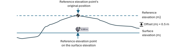
The default offset value is 0 meters. The minimum value is 0 meters, and the maximum value is infinite.
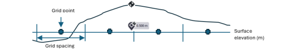
Grid Spacing: A grid is a network of evenly spaced lines that form square cells within the inspection area. The Grid Spacing refers to the size of each square cell used for inspection. If the grid spacing is 25 centimeters, each cell is 25 centimeters by 25 centimeters.
Grid spacing determines the resolution of the data collected and analyzed. Smaller grid spacing provides more detailed information, which can lead to more accurate cut and fill calculations but may require more time and resources to process and to visualize.
The default grid spacing value is 0.25 meters (or 1 feet). The minimum value is 0.10 meters (or 0.328 feet), and the maximum value is 100 meters (or 328 feet).
Tolerance: It defines the acceptable limits for the variations in elevation, ensuring that the floor surface meets the required standards for evenness and levelness. For example, if the tolerance is set to ±10 mm, any point on the floor surface with an elevation deviation within this range (from -10 mm to +10 mm) would be considered acceptable.
The default tolerance value is 3 millimeters (0.125 feet). The minimum value is 1 millimeter (or 0.039 feet), and the maximum value is 3200 millimeters (or 1259 feet).
-
-
Optionally, tap
 Settings to access additional inspection settings.
Display: Choose:
-
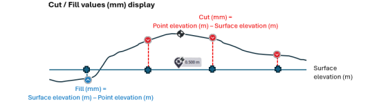
Cut/Fill Values to display the amount of material that needs to be removed from (Cut) or added to (Fill) the floor surface to achieve the desired level. Cut/Fill Values, in millimeters or inches, are always positive regardless of whether they represent a cut or a fill.
-
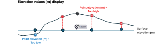
Elevation Values to represent the actual elevation of the grid points in meters (or feet) based on the reference or surface elevation, including an offset.
Grid Points: It refers to a point at the center of a square cell and its value is the average elevation of points within a radius of 1/5 of the cell size. For a 25-centimeter cell size, all elevation points within a 5-centimeter radius are used to determine the elevation value of this point.
Turn the option On to display these points on the inspection result. Turn the option Off to hide them.
The option can be enabled (or disabled) before (or after) computing an inspection.
Grid Point Labels: This refers to the elevation value of a grid point. It is the average elevation at the cell's center, with a ratio of 1/5. For a 25-centimeter cell size, all points within a 5-centimeter radius are used to determine the elevation value of the grid point.
Legend: Is a visual representation of data values using colors. It offers a scale to help interpret the colors on an inspection map, indicating which colors correspond to specific data values or ranges.
Auto-Extract Floor: The option, when it is enabled, allows the floor to be extracted from the inspection area. It uses an algorithm that processes the point cloud, using only the extracted ground for inspection calculations. To avoid extracting the floor, simply disable the option.
Inspection Default Slice Size: This setting determines the default slice size of the floor or ground that will be assessed during earthwork operations.
After selecting the reference elevation point, a slice of the default size is extracted and previewed. This size is used to all current and subsequent inspections, with the color gradient applied only within this area. Adjusting the default slice size will change the Limit Box Vertical Extent value of the limit box, but changing the Limit Box Vertical Extent value will not affect the default slice size.
The default slice size value is 50 millimeters. The minimum value is 10 millimeters, and the maximum value is 3200 millimeters.
-
-
Tap Generate to compute and display the inspection in the
 Map View.
The Cut and Fill inspection will fail in the following conditions:
- The inspection area for the operation is empty, there is no data to process*.
- The Auto-Extract Floor process returns an empty or insufficient point cloud. The algorithm is unable to detect any floor surfaces within the inspection area.
(*) If you encounter a situation where no points are visible or the area appears empty, ensure that the reference elevation point is correctly defined and the offset value is set correctly. Incorrect offset can cause the points to be placed outside the visible area or in unexpected locations.With the Grid Points option set to On, a first prompt appears. Zoom in to a scale of one meter (or 3.28 feet) to see the grid points (
 and
and  ) over the inspection result.
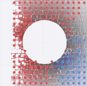
With the Grid Points Labels option set to On, a second prompt appears. Zoom in further (until to reach 0.2 meters (0.65 feet)) to display the grid points with labels that show measurement values without unit
 . The labels can show either Cut / Fill values or Elevation values, depending on the option selected in the Settings.
 The red label indicates the grid point with the largest cut value.
 The blue label indicates the grid point with the largest fill value.
 With the Grid Points option set to Off:
-
Tap
Settings. -
Turn the Grid Points option On. The same prompts appear.
-
Zoom in to display grid points and / or grid point labels.
With the Legend option set to On, the visual representation of data values using colors is displayed. It can be moved anywhere in the
Map View.With the Auto-Extract Floor option set to:
-
Off: The floor is not extracted from the scene.
-
On: The floor is extracted from the scene.
-
-
Tap a grid point to expand the card and tap again to shrink the card.
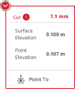
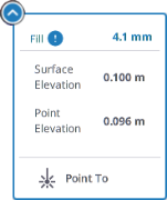
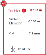
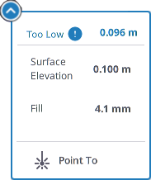
Each card displays the following details:
-
Cut / Fill values (in millimeters or inches):
Cut value indicates the depth of material that needs to be removed from to the selected grid point elevation to bring it down to the surface elevation level. Fill value indicates the depth of material that needs to be added to the selected grid point elevation to raise it to the surface elevation level.
-
Surface Elevation value (in meters (or feet)) corresponds to:
Reference elevation value + Offset value if
Surface Above Reference is chosen.Reference elevation value - Offset value if
Surface Below Reference is chosen. -
Point Elevation value (in meters or feet) is the elevation at the grid point position, compared to the surface elevation. It is:
Too High when the grid point's elevation is above the surface elevation level. Too Low when the grid point's elevation is below the surface elevation level.
-
-
Optionally, use the
Laser Pointer to highlight an inspection grid point in the scene and on the inspection result. The highlighted grid point flashes as follows:
You need to be connected to your scanner and make sure your last station is registered to or within the inspection selection.
-
Optionally, adjust the settings. The inspection is then canceled. Tap Generate again to recompute a new inspection.
If you leave the Cut and Fill tool (or switch to another tool) without saving the inspection, an error message will pop up prompting you to proceed or not. Tapping Continue will cancel the inspection and close the tool.
-
Tap Save. The inspection result is saved and placed in the Inspection panel. At the same time, a report is automatically created and displayed for you to review (see Report).
-
Review the report and close it.
-
-
If there are some inspection results available, they are listed in the Inspection panel. Tap a card to select and display the inspection result.
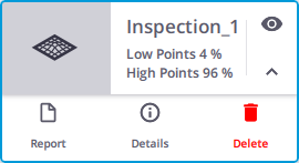
Tap:
 Show/Hide Inspection to hide the inspection result (and the legend).
  Show/Hide Inspection to show the inspection result (and the legend).
 Report to generate and display the report. See Report.
 Export Grid Points to export the grid points from the inspection result as a CSV file. See Export Grid Points.
 Details to view the inspection result in detail.
 Delete to delete the inspection result.
Deleting an inspection result is permanent and cannot be undone.
Breaking a registration link in a registered and refined project can change the spatial relationships of the data, which may make the already saved inspection results inaccurate.
Created inspection results can be sorted by Name or Date Created in Ascending Order (or Descending Order).
Tap  Edit to modify the current inspection results. The Inspect panel opens with the defined settings. Optionally, adjust the settings and tap again Calculate to compute a preview of the inspection.
Tap Generate Report. The Cut and Fill Inspection Report opens and displays the following information:
-
Project Image: The thumbnail of the first station of the project to be inspected.
-
Inspection Name: The defined name or the default name (Inspection N).
-
Inspection Status: PASS (or FAIL) indicates whether the evaluated floor area meets the specified cut and fill criteria.
-
Inspection Snapshot: A snapshot of the inspection result. When a limit box is set, the report will zoom in on that specific area to take a screen shot. If no limit box is set, the report will zoom out to all extents to capture a screen shot of the entire inspection cloud.
To display a snapshot of an inspection with the grid points, check the Include Grid Points option in Edit Report Details. See Edit.
-
Scanner Information: Details about the scanner used for the inspection.
-
Points Summary: The total of grid points, the number and percentage of grid points that are above the specified tolerance, the number and percentage of grid points that are below the specified tolerance, the number and percentage of grid points that fall within the specified tolerance, and the percentage of grid points that need to be within the specified tolerance for the inspection to pass.
-
Elevation Summary: The baseline elevation used for the inspection, the offset, the surface elevation, the acceptable range of elevation variation, the highest elevation point and the lowest elevation point recorded during the inspection, and the largest cut and fill values.
-
Area Summary: The area covered during the inspection (Area), along with the area above the tolerance (High Area) and the area below the tolerance (Low Area). The Area is calculated using the formula:
Area (Total Points x Grid Spacing2) = High Area (High Points x Grid Spacing2) + Tolerance Area (Points With Tolerance x Grid Spacing2) + Low Area (Low Points x Grid Spacing2)
Tap Edit. From the opened Edit Report Details panel, add the information about your company (Logo, Name and Website), the information about you (name and title), and additional images. If required:
- Change the Threshold value for the Pass Percentage (which refers to the percentage of points that need to be within the specified tolerance for the inspection to pass).
- Check the Include Grid Points option to display the grid points over the inspection result displayed in the report.
Tap Save to save the report in a PDF or HTML format file.
Tap Export Grid Points to export the grid points of a generated inspection as a CSV file. The file will include the following information: Point, Coordinates (X, Y, Z or N, E, El) Elevation value, and Cut/Fill value. The coordinate convention depends on the setting in Settings > Units.
Points are named as follows: "Number_F" for fill points and "Number_C" for cut points. Numbers are assigned sequentially, starting from the bottom-left corner of the inspection area when viewed from above.
