Understanding Aerial Photogrammetry Data
Note: To ensure the highest performance and most trouble-free viewing experience when working with aerial photo stations, you must ensure your graphics card has been updated with the latest driver (software) available. See Update and Configure Your Graphics/Video Driver for instructions.
A UAS (unmanned aircraft system) aerial mapping and survey system generates an aerial survey flight mission, which is an interconnected series of aerial photo station images that are intended to be processed as a single unit and used for surveying purposes. An aerial photo station is created each time an aerial photo is taken during a flight mission. It defines a point and includes raw sensor values (orientation and tilt), coordinate data, and a photo image. The following image shows the aerial photo stations created for a flight mission. The station location and altitude determine the actual overlap between images taken from each station.
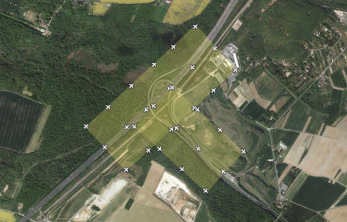
A single flight mission can include one or more flight blocks. A flight block is intended to cover a single polygonal area on the earth’s surface. The previous image shows two flight blocks included in a single flight mission. A flight block is defined by a flight plan, which specifies parameters that define the proper flight path a UAS must follow to produce a single flight block. Parameters include the geographical location of the area, the desired height of the aerial photo station above the ground, and the percentage of forward and lateral photo image overlap.
The UAS Importer has been enhanced to allow you to import geotagged aerial image data from virtually any UAS camera regardless of the make and model. TBC includes an extensive list of predefined camera specifications that can be automatically applied when you perform the import, or you can import data from UAS cameras not stored in TBC by manually entering required specifications (sensor focal length and sensor pixel size) directly into fields provided in the Import pane prior to import. These custom specifications can be saved and re-applied when image data is again imported from the same UAS camera. Additionally, the Import UAS Data command pane now displays the camera maker and model along with the sensor size in pixels (if provided in the image's EXIF metadata).
There are two basic categories of importable aerial survey data: data that does not include trajectory information (autonomous) and data that does.
- UAS data without a trajectory - After importing UAS data that does not include a trajectory (autonomous), you must perform a relative adjustment that uses automatically found tie points to adjust the photo stations relative to each other. To more precisely locate the station points on the ground, you will need to make photogrammetry measurements to ground control points (GCPs), which are accurately surveyed features (for example, targets), that are visible in multiple photos. You can then use the measured GCPs to provide the control necessary to perform an absolute adjustment to the ground. A camera calibration is included in the absolute adjustment process to provide the highest precision.
- UAS data with a tracectory - When, you import trajectory-based UAS data, a raw data file containing continuous data with event markers (captured with the on-board GNSS receiver) is included . To process the trajectory in the project, you must also import a raw data file containing the base station coordinate (must be Control Quality) that will be used to process the trajectory coordinates.
Notes: For more information on working with trajectories, see Process Event Data, Trajectories and Vectors, and Process Baselines.
After you process a trajectory from the imported GNSS data, you can perform a relative adjustment that uses automatically found tie points to adjust the photo stations relative to each other. If the quality of the trajectory is sufficient, an absolute adjustment is automatically performed when the relative adjustment is complete, using the trajectory to provide the control necessary to adjust photo stations to the ground. A camera calibration is included in the absolute adjustment process to ensure the highest precision.
Trajectory-enabled UAS data does not necessarily require GCPs to perform an absolute adjustment. However, they may be necessary if, for example, the flight mission includes only a single flight block (there is no second "crossing" flight block flown in an overlapping diagonal patter over the same area as the first flight block), the trajectory is of inadequate quality, or you want to provide quality checks.
After you import and adjust aerial photo stations, you can create any of the following deliverables using the Create Deliverables command.
- orthomosaic - A photo composed of multiple orthophotos.
- raster-based digital surface model (DSM) - A representation of the topography of the earth or another surface in digital format (that is, by coordinates and numerical descriptions of altitude). DSMs are often used in geographic information systems. A DSM can be represented as a raster (a grid of cells, also known as a height map when representing elevation) or as a vector-based triangulated irregular network (TIN).
- point cloud - A set of vertices in a three-dimensional coordinate system that are usually defined by X, Y, and Z coordinates, and are intended to be representative of the external surface of an object. For more information, see Understanding Point Cloud Data.
Baseline Processing for GNSS trajectories
TBC supports GNSS trajectory baseline processing from:
|
Vendor |
Drone |
Model Name |
TBC Version |
|
DJI |
Mavic 3 |
M3E |
5.81 |
|
DJI |
Matrice 300, Matrice 350, Matrice 400 |
ZenmuseP1 |
5.80 |
|
DJI |
Phantom 4 RTK |
FC6310R |
5.50 |
|
DJI |
Mavic 3 |
M3M |
2024.1 |
|
DJI |
Matrice 300, Matrice 350, Matrice 400 |
L2 |
2024.1 |
|
DJI |
Matrice 4 |
M4E |
2025.1 |
|
Skydio |
X10 |
VT300 |
2024.1 |
|
Skydio |
X10 |
V100 |
2024.1 |
|
FreeFly |
Astro |
ILCE-7RM4A |
2024.1 |
|
FreeFly |
Astro |
ILX-LR1 |
2024.1 |
TBC checks during the import of the JPG images for other relevant files.
If you run your drone flight in RTK mode and collect a complete RTK data set during the flight, TBC searches the image folder for the following files:
- Timestamp information
- Kinematic trajectory file
Note: These files are automatically imported with your drone images to ensure the trajectory data is correctly tagged to the images. Keep the data set complete, and do not delete single images of the flight.
In addition to the kinematic data from your drone, to perform a successful baseline processing correction you must collect your static base station data (receiver) during the drone flight. The static base station can be any of the following:
- local base (*.t0x, from Trimble)
- local base (RINEX from third-parties)
- CORS data from a VRS network
