Adjust Aerial Photo Stations
Before you can use imported aerial photo station data to create aerial survey deliverables, you must adjust the photo stations using the Adjust Photo Stations commands as described here. The Adjust Photo Stations commands allows you to make two types of aerial photo station adjustments, which must be performed in the sequence shown here:
- Relative adjustment - In this adjustment, TBC automatically identifies tie points in aerial images and matches them to correctly orient the aerial photo stations to each other and reference them to the ground based on autonomous GNSS positions recorded when the photo images are taken. This is the minimal adjustment required prior to creating aerial survey deliverables.
Note: Deliverables created after only a relative station adjustment has been performed will be of low quality. The georeferenced position of the deliverables may be incorrect and there may be misalignment in the point cloud and orthophoto. If applicable, it is recommended that you perform an absolute adjustment prior to creating deliverables.
- Absolute adjustment - In this adjustment, TBC adjusts the photo station points more precisely to the ground.
- For autonomous UAS data, three or more ground control points (GCPs) are required.
- For trajectory-enabled UAS data, a trajectory of appropriate quality is required.
A camera calibration is included in the absolute adjustment process to provide the highest precision.
The adjustment process you use depends on the UAS data you want to process and adjust:
- Autonomous UAS data with no GCPs - You can perform only a relative adjustment. You do not have adequate data to perform an absolute adjustment. You can create deliverables after the relative adjustment is complete.
- Autonomous UAS data with GCPs - You can first perform a relative adjustment. Optionally, you can then measure the GCPs to perform an absolute adjustment to obtain higher precision. You can create deliverables after either the relative adjustment or the optional absolute adjustment is complete.
- Trajectory-enabled UAS data (baseline processed) with no GCPs - You can perform a relative adjustment and an absolute adjustment will be performed automatically immediately after the relative adjustment is complete based on the processed trajectory data. You can create deliverables after the absolute adjustment is complete.
- Trajectory-enabled UAS data (baseline processed) with GCPs - You can perform a relative adjustment and an absolute adjustment will be performed automatically immediately after the relative adjustment is complete based on the processed trajectory data. Optionally, you can then measure the GCPs to perform a second absolute adjustment to obtain the highest accuracy. You can create deliverables after the first or, optionally, the second absolute adjustment is complete.
Notes:
- If you need to merge multiple flight missions in your project, you must do so before performing an aerial photo station adjustment.
- If you are working with DJI aerial survey data, see Import and Process DJI Aerial Survey Data for instructions.
- TBC applies radiometric corrections to aerial photo images automatically during the photo station adjustment process to improve the interpretability and quality of the images. The corrections compensate for over- or under-lit areas within images (due to image exposure, focal length, the sun's azimuth/elevation, and atmospheric conditions), resulting in images that are more evenly lit, and in which fine detail is more easily discernible. The radiometric corrections, which are applied very quickly during the adjustment process (minimal impact on processing time), are contained in small RDX (.rdx) files stored in your project folder (one for each photo image).
- If GNSS quality is low and the EXIF height values from the imported drone images are incorrect (for example, due to the wrong coordinate system being used), you can right-click on the Flight Block in the Project Explorer and select the Set Height Shift command, which enables you to perform a GNSS height shift. If necessary, you can use the Inverse command in the 3D View to measure between the drones and ground control points to determine the correct height shift value to apply using the Set Height Shift command.
This topic includes the following procedures:
- To process a trajectory (trajectory-enabled UAS data only)
- To perform a relative adjustment (autonomous and trajectory-enabled UAS data) and absolute adjustment (trajectory-enabled UAS data only)
- To perform an absolute adjustment of aerial photo stations using GCPs
Prerequisites:
See the Subscription Plans page. For a license matrix by command, see the License page in the TBC Community. Also see View and manage licensed features.
To process a trajectory (trajectory-enabled UAS data only):
If you are adjusting photo stations recorded with a trajectory-enabled UAS, do the following:
- Verify the required data has been imported into your project.
- Verify that your project is configured with the correct coordinate system for the flight mission.
- To ensure your project is correctly configured to ensure the highest quality trajectory, select Project Settings in the Quick Access Toolbar. Then select Baseline Processing > Processing and select Dual Frequency (L1, L2) for the Frequency setting and Fixed only for the Trajectory solution type.
Note: When working with trajectory-enabled UAS data, you can select to use the project template Trimble UX5 HP Solution Template in which these settings are already set. In Trimble Business Center, select File > New, select the template, and click OK.
- Process baselines for the data in the related receiver raw data file to create a high-quality trajectory.
For more information, see Process Event Data and Trajectories and Vectors.
Note: To perform a trajectory-enabled photo station adjustment, the base station coordinate must be Control Quality. If it is not, a message displays when you attempt to perform the adjustment stating that the trajectory is not of adequate quality to perform the adjustment.
The trajectory will provide ground control when performing an absolute adjustment later in this procedure.
To perform a relative adjustment (autonomous and trajectory-enabled UAS data) and absolute adjustment (trajectory-enabled UAS data only):
- If you have not already done so, verify that your project is configured with the correct coordinate system for the flight mission.
- Do one of the following:
- Select Adjust Photo Stations in Photogrammetry > Adjust.
- In the Project Explorer or graphic view, right-click the flight mission for which you want to adjust aerial photo stations and select Adjust Photo Stations in the context menu.
The Adjust Photo Stations command pane displays.
- If it is not already selected, in the Mission drop-down list select the flight mission for which you want to adjust aerial photo stations.
Note: The adjustment process, as described in the next step, can take a long period of time to complete if you are working with a large amount of data. If your computer goes to "sleep" during processing, the process will stop and will not re-continue until the computer is "awakened." To prevent this from happening, you can extend the period before which your computer goes sleep by selecting Power Options in your Windows Control Panel.
- On the Adjustment tab:
- To enable automatic GCP target detection, check the Automatic GCP detection checkbox, then select Ground control points to define candidates for the automatic GCP target detection.
- Click the Adjust button.
The aerial photo stations within the selected flight mission are adjusted using tie points and autonomous GNSS positions. The Process View tab displays to show the progress of the process.
Note: If you have selected to display additional process view notices in the Process Monitoring settings in the Optionsdialog, the progress also displays on the Trimble Business Center taskbar button by way of a colored bar moving across the button's background. When the process is complete, a checkmark is displayed on the button and a notification is displayed in a pop-up Desktop Alert.
To cancel processing, click the Cancel button on the Process View tab.
If you are adjusting trajectory-enabled UAS data and a trajectory of adequate quality has been created in the project, the absolute adjustment begins immediately after the relative adjustment successfully completes.
Note: To perform a trajectory-enabled photo station adjustment, the base station coordinate must be Control Quality. If it is not, a message displays when you attempt to perform the adjustment stating that the trajectory is not of adequate quality to perform the adjustment.
When processing is complete, the Apply Adjustment and Discard buttons are displayed on the Process View tab.
- On the Process View tab, click the Apply Adjustment button to save the adjustment results in the project.
A message is displayed asking if you want to view the Flight Mission Adjustment report. Click Yes to view the PDF report in Adobe Acrobat Reader. For more information, see Run a Flight Mission Adjustment Report.
- If your project includes autonomous UAS data with no GCPs, the relative adjustment process is complete and the results are displayed on the Results tab in the Adjust Photo Stations command pane. You do not have adequate data to perform an absolute adjustment. You can now create deliverables from the adjusted data. See Create Aerial Survey Deliverables.
- If your project includes autonomous UAS data with GCPs, the relative adjustment process is complete and the results are displayed on the Results tab in the Adjust Photo Stations command pane. Optionally, you can now measure the GCPs to perform an absolute adjustment. See "To perform an absolute adjustment of aerial photo stations using GCPs" later in this topic.
- If your project includes trajectory-enabled UAS data (baseline processed) with no GCPs, the relative and absolute adjustment processes are complete and the results are displayed on the Results tab in the Adjust Photo Stations command pane. You can now create deliverables from the adjusted data. See Create Aerial Survey Deliverables.
- If your project includes trajectory-enabled UAS data (baseline processed) with GCPs, the relative and absolute adjustment processes are complete and the results are displayed on the Results tab in the Adjust Photo Stations command pane. Optionally, you can now measure the GCPs to perform a second absolute adjustment for the highest precision. See "To perform an absolute adjustment of aerial photo stations using GCPs" later in this topic. To create deliverables from the adjusted data, see Create Aerial Survey Deliverables.
By viewing the adjustment results on the Results tab, you can make some determination about the precision of the adjusted aerial survey data.
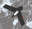
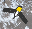
A section of each aerial photo station icon displayed in the Project Explorer and Plan View changes from black to yellow to indicate that a relative adjustment has been performed.
Before adjustment:
After relative adjustment:
To perform an absolute adjustment of aerial photo stations using GCPs:
This procedure is required if:
- Your project includes autonomous UAS data with GCPs, the relative adjustment process is complete, and you now want to measure the GCPs to perform an absolute adjustment with higher accuracy.
- Your project includes trajectory-enabled UAS data (baseline processed) with GCPs, the relative and absolute adjustment processes are complete, and you want to measure the GCPs to perform a second absolute adjustment for the highest accuracy.
Notes:
- Before performing this absolute adjustment, you must perform a relative adjustment as described in the previous procedure.
- Trajectory-enabled UAS data does not typically require GCPs to perform an absolute adjustment. Your stations were automatically adjusted absolutely using the trajectory for control, as described in the last procedure. However, they may be necessary if, for example, the flight mission includes only a single flight block (there is no second "crossing" flight block flown in an overlapping diagonal pattern over the same area as the first flight block), the trajectory is of inadequate quality, or you want to provide quality checks.
- If the ground control points (GCPs) in your project were derived from GNSS data and you are using a Survey Quality geoid, you need to set the geoid model to Survey Quality in the Change Coordinate System dialog to avoid degrading the quality of the elevation of the points. If you do not have a Survey Quality geoid, you will not be able to use GNSS-derived control points.
- Select Adjust Photo Stations with GCPs in Photogrammetry > Adjust to display the Adjust Photo Stations with GCPs command pane.
- Verify the correct flight mission is selected in the Mission drop-down list.
- On the Absolute Adjustment tab, click in the Point ID field, then select a Control Point in the Plan View or the Project Explorer pane.
- Click the Add button
 located to the right of the Point ID field, or press the Enter key.
The following occur:
- The selected point is added to the Control Points list.
- The aerial photo stations with photo images most likely to include the control point are displayed in the Photo stations list.
- The photo image from the first station in the Photo stations list is displayed on a new Station View tab. The associated control point is used to center the photo image on the tab.
- Optionally, in the Status drop-down list for the point in the Control Points list, change the selection:
- Enabled - Include all photogrammetry observations of the control point in the adjustment.
- As check - Make photogrammetry observations to the control point to calculate the point's position, but do not include the control point in the adjustment. This control point will be used as a check for precision.
- Disabled - Do not use the control point in the adjustment.
- Do one of the following:
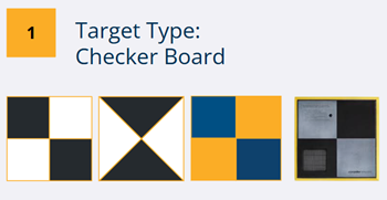
- To enable automatic GCP target detection, add measured ground control points via point ID, then click Run automatic target detection. Automatic target detection uses checkerboard targets, as shown in the example below:
Note: For the highest success rate, ensure the following:
- Images must be high quality (no blurry or low-contrast images).
- Images must be geolocated within 5-10 meters (this accuracy level is enough in WGS84 (EPSG:4326)).
- Images must be taken at nadir or slightly oblique angles.
- Images should be at least 20 times the average GSD of the project.
- GCP targets should be black and white, though other colors may work.
- GCP targets must be at least 10 meters from each other.
- GCPs must be imported to TBC and selected from the TBC project.Workflow tip: After adding GCPs from the project into the control point list, run the automatic target detection and then apply the adjustment. Generate the Flight Mission Adjustment report and review the Ground Point Control Statistics. If errors are higher than expected, review the individual photo stations and verify the extraction worked as expected. If the extraction is poor quality, use manual selection to override the automatic detection.
Continue with step 9.
- To manually select the first ground control point (GCP) you want to measure, do either of the following:
- Click in the Point ID field and then select the control point in the Project Explorer or graphic view.
- Type the control point ID in the Point ID field.
Continue with step 6.
Note: Only control points with coordinate quality of Control or Survey can be used in the adjustment.
- To enable automatic GCP target detection, add measured ground control points via point ID, then click Run automatic target detection. Automatic target detection uses checkerboard targets, as shown in the example below:
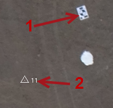
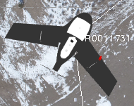
- To make a photogrammetry observation to the control point in the newly displayed Station View tab, click in the Pixel Picker field. Then, using the Pixel Picker view control, click as accurately as possible on the control point target or feature in the photo image.
The target or feature (1 in the image below) should be located in the proximity of the true control point location (2).
 More about using the Pixel Picker...
The station's Status changes to Enabled in the Photo stations list.
By default, the Automatically advance on select check box is checked to specify that the next station in the list be automatically selected each time you make a photogrammetry observation.
- For each additional station you want to use to make a photogrammetry observation to the selected ground control point, repeat step 6.
An epipolar line representing each photogrammetry observation is displayed in subsequent photo images and can be used to more easily locate the target or feature. To increase the length of the epipolar line , select Project Settings in the Quick Access Toolbar. Then select View > Referenced Image > Maximum length for line-of-sight rays.
The stations positioned higher in the Station list are most likely to provide a view of the control point. To ensure the highest precision, each GCP target requires a minimum of two observations. However, to ensure good block geometry and redundancy, it is recommended that the two observations come from different flight strips (paths) and you include three additional observations as checks.
- For each additional control point you want to include in the adjustment, repeat this procedure.
Note: The adjustment process, as described in the next step, can take a long period of time to complete if you are working with a large amount of data. If your computer goes to "sleep" during processing, the process will stop and will not re-continue until the computer is "awakened." To prevent this from happening, you can extend the period before which your computer goes sleep by selecting Power Options in your Windows Control Panel.
- When you are done, click the Adjust button.
The selected aerial photo stations are adjusted using the control points. The Process View tab displays to show the progress of the process.
Note: If you have selected to display additional process view notices in the Process Monitoring settings in the Optionsdialog, the progress also displays on the Trimble Business Center taskbar button by way of a colored bar moving across the button's background. When the process is complete, a checkmark is displayed on the button and a notification is displayed in a pop-up Desktop Alert.
To cancel processing, click the Cancel button on the Process View tab.
If processing completes successfully, the Apply Adjustment and Discard buttons are displayed on the Process View tab.
If processing fails, a Fail indicator and a Show Log File button are displayed on the Process View tab. Click this button to view a log of the errors and warnings that occurred during processing. (If necessary, you can provide this information to technical support if you contact them for assistance.) The log file is named <MissionName><ID>_ErrorLog.txt and is stored in the project folder.
- On the Process View tab, click Apply Adjustment to save the adjustment results in the project.
A message is displayed asking if you want to view the Flight Mission Adjustment report. Click Yes to view the PDF report in Adobe Acrobat Reader. For more information, see Run a Flight Mission Adjustment Report.
- Select the Results tab to view information about the control point adjustment.
In addition to the information displayed as a result of the relative adjustment, the Results tab now also includes residuals for photogrammetry observations. By viewing the adjustment results, you can make some determination about the precision of the adjusted aerial survey data.
Optionally, based on your results, you may choose to remove one or more ground control points from the adjustment. On the Control Points tab, select "Disabled" for the point in the Status drop-down list and click the Adjust with Control Points button to re-adjust the aerial photo stations.
Information displayed on the Results tab is also displayed in the Flight Mission Adjustment Report. For more explanation of this information, see Run a Flight Mission Adjustment Report.
A section of each aerial photo station icon displayed in the Project Explorer and Plan View changes to white to indicate that an absolute adjustment has been performed.
After adjustment is complete, you are ready to create aerial survey deliverables.
