Compute Volumes for a Region
Use the Compute Region Volume command to quickly calculate the cut and fill volumes, areas, centers of mass, and the difference between the volumes of a specific region within your job site. This can give you a 'quick snapshot' of earthwork requirements as you iterate through performing a site mass haul manually.
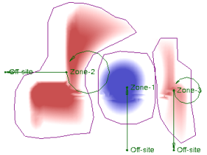
This command helps you determine how to balance volumes on a site. It provides a quick way for you start with an area to balance and then increase or decrease what is included until the cut volume balances the fill. A haul cost can then be determined by measuring the distance from the center of mass of one area to the center of mass of another. To help visualize this hauling distance, the command draws a connection linestring between the cut and fill centers of mass. Although the site mass haul workflow is automated and provides this information as well, Compute Region Volume allows you to have more granular control by viewing site volumes one region at a time.
Caution: Using this command, it is possible to miss volumes in areas or to count volumes in overlapping areas twice. In addition, this command does not consider strata or material density states (shrinkage, bulkage, and compaction).When balancing cut and fill volumes, you should consider the volume of the entire site. One way to do this is by running an Earthwork Report.
Using with a Site Mass Haul Analysis
You can use the region boundary polygons created by this command as haul zones when you analyze mass haul needs for a site. The Create Site Mass Haul Analysis command creates a label at the center of mass of each zone, and enables you to consider shrinkage, bulkage, and compaction of the in situ materials.
Tip: Before you run this command, you may want to create two layers: one named Cut that uses your cut color, and one named Fill that uses your fill color. Then, when you create a region boundary for cut and fill areas, and put them on their respective layers, they will be colored accordingly.
Prerequisites:
- Licensed module; See the Subscription Plans page. For a license matrix by command, see the License page in the TBC Community. Also see View and manage licensed features.
- Cut/fill map
To access the command:
- Select Compute Region Volume in Site Mass Haul > Cut/Fill Map.
To compute the volumes of a specific area:
- In the Name box, type an identifier for the linestring as you want it to appear in the Selection Explorer and graphic views. You can also use the name to select the volume boundary in the Advanced Select command.
- Select a cut/fill map to analyze in the Cut/Fill map list or select <New> to create a cut/fill map. You may also use an Isopach surface rather than a cut/fill map. Isopach surfaces are created when you run the Earthwork report and enable the option to save the intermediate data.
- Select the layer on which you want the volume boundary to reside in the Layer list, or select <<New Layer>> to create a new layer.
- To use an existing region (or edit or recalculate volumes for a previously-computed region), pick the region boundary from the Optional existing boundary box. Then skip to step 10.
- If you are creating a new region boundary, ensure that Expand is selected as the Boundary Edit option.
- To draw a boundary, select one of the following options under Method to Add Points:
- Specify individual points - Select individual points to draw a polyline to define the boundary used in the calculation, or add individual points in the Specify individual points box. Click Compute to close the shape and calculate the results. Skip to step 10.
- Stream points - Draw a path around the boundary to be used in the calculation.
- In the Filter Settings group, select a Filter type from the list:
- Circle - In the Radius box, specify the minimum radial distance from the last point that the next point can be added.
- Tube - In the Length and Width boxes, specify the minimum rectangular distance from the last point that the next point can be added. Polylines are drawn in 2D, so this is not a 3D filter.
Tip: Start with a filter radius/length of 3 feet/1 meter. Then adjust the tolerance up or down depending on your needs.
Note: If you start a new linestring, the same filter settings are used until you change them.
- Click in the Next points box.
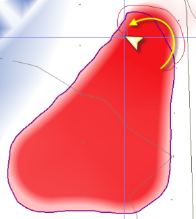
- Pick the first point of the boundary in the Plan View, hold down the mouse button, and move along the path. Points are created at a regular interval, based on the tolerance set in Filter Settings. At the end of the boundary, release the button. The first segment is connected to the last to close the boundary, and the cut and fill volume calculations appear in the Results pane at the bottom.
- Review the cut volume, fill volume, and differences in the Results area.
- Click Save result to create a new region volume results node in the project. View or edit this node in the Properties frame. See Region Volume Options. Note that before you can save the results, you must Name the results report (see step 1). After saving a result, the command remains locked to that boundary so you may continue to Expand or Trim it. If you make edits, click Save result to update the node.
Note: If the difference between cut and fill is less than 2%, it will not be shown due to round-off.
Tip: You can cut-and-paste text from the results to create a label of the volumes for the region.
- Click Save result to create a new region volume results node in the project. View or edit this node in the Properties frame. See Region Volume Options. Note that before you can save the results, you must Name the results report (see step 1). After saving a result, the command remains locked to that boundary so you may continue to Expand or Trim it. If you make edits, click Save result to update the node.
- To draw a new region, click New at the bottom of the command pane to clear the current boundary, and then repeat steps 6 - 10.
To edit the boundary of a volume region:
- Pick the region from the Optional existing boundary box.
- Select a Boundary Edit option:
- Expand - Select this to initially create the volume boundary or to enlarge it. Then pick a point inside the region, loop out around the area to add, and then click back into the region.
- Trim - Select this to reduce the size of the volume boundary. Then pick a point outside the region, loop in around the area to add, and then click back outside the region.

- Review the new cut volume, fill volume, and differences in the Results area.
To manage saved region volumes
Once a region volume is saved, it appears as a Region Volume node in the Project Explorer under its respective Cut/Fill Map.
- To edit a boundary: Right-click the node and select Edit. The command pane reopens, allowing you to use the Expand or Trim boundary edit options. Review the updated calculations in the Results area.
- To delete a region: Right-click the node and select Delete. The saved entity, solid fill, and center of mass connection line will be removed.
- To locate a region: Double-click the node in the Project Explorer to highlight the boundary in the graphic view.
To generate a Region Volume Report
Use the Region Volume Report command to export a comprehensive Excel spreadsheet detailing all saved region volumes within your project.
- In the Project Explorer, right-click the Cut/Fill Map node and select Region Volume Report. Alternatively, run the command from the Command Pane. This generates an Excel file containing all saved Region Volume entities in the project, sorted alphabetically.
- The report includes the Name, Cut/Fill Map, Cut Volume, Cut Area, Cut/Fill Centers of Mass, Fill Volume, Fill Area, Net Volume, Net Type, and Center of Mass 3D Distance.
Dependencies:
- None
