Insert a Trench Template
After you have created a utility runand one or more trench templates, use the Insert Trench Template command to insert the templates into the run. These templates include instructions that define the cross-section lines required to build the trench (for example, the various offsets and side slopes/laybacks from the pipe).
Each trench template you insert defines the trench from the station where it is inserted until the station where the next template is inserted (or to the end of the utility run). Typically, you only need to insert a trench template at the POB of the run. Additional templates will automatically be added at nodes to control widening around them. You can also manually insert a template at a specific location where conditions change, such as under a roadway where you want to use different materials for the backfill.
Note: For most projects, you can insert just one template at the starting station of a run and the entire run's trench will be modeled appropriately. You can also insert a template at a later station to skip a section of trench by changing that template's Trench template property to None to make it null from the insertion station until the next valid template.
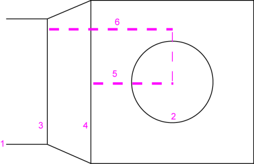
- Trench edge
- Node (in this case, a schematic manhole diameter)
- Auto-inserted trench template (based on dimension 5 below)
- Auto-inserted trench template (based on dimension 6 below)
- Template is inserted at (1/2 node width (in this case, the manhole radius) + its wall thickness) from the node's center.
- Another template is inserted at (1/2 width + wall thickness + offset (as defined on the Trench Template Manager's Basic tab) from the node's center.
The trench surface's wall transitions between the two templates.
Figure: Trench template transition at a manhole utility node (Plan View)
Each trench template can be inserted into a run at specific stations, and multiple templates can be inserted into one run, but more commonly one template can be used for multiple runs, especially when used for storm drains which are fairly uniform. Generally, (with Adjust at nodes enabled) you should not need to make multiple templates for a single type of network. The run, the target surface, and the trench template can be used to form a trench surface. Once inserted, trench templates are listed under the run the Project Explorer in station order.
Note: You can make and manually insert additional trench templates to model transitions at the junction of two or more utility runs.
Prerequisites:
- Licensed module, See the Subscription Plans page. For a license matrix by command, see the License page in the TBC Community. Also see View and manage licensed features.
- Utility run
- Trench template
To access the command:
- Select Insert Trench Template in Utility > Trench.
- In Project Explorer, right-click the utility run into which you want to insert a template, and select Insert Trench Template in the context menu.
To insert a trench template:
- In the Utility run list, select the existing run into which you want to insert the template.
- In the Station field, specify where along the run you want the template to be inserted:
- Type in the station value or distance along.
- Pick the station graphically in the Plan View. Optionally, right-click in the view and select one of the additional options for selecting the station.
- In the Trench template list, select the template to insert.
- To have the template widen/deepen when it encounters a node along the run (based on parameters on the Basic tab in the Trench Template Manager), check the Adjust at nodes box.
Note: You should confirm the previously specified offsets from the sides and bottom of the node in the template manager.
- Click OK. The new template is inserted into the run at the specified station, and it displays as a new object beneath the run in the Project Explorer.
