Create and Edit a Utility Trench Surface
Use the Create Trench Surface command to create a surface that models the bottom and side slopes of a utility line trench. A trench surface can be created after one or more trench templates are inserted along a utility run. You can edit trench surfaces like other surfaces, e.g., you can add/remove members and breaklines. You can also send trench surfaces to the field to be constructed.
The same calculation engine used to generate corridor surface models is used to create trench surfaces, so there are similar (yet inconsequential) limits to the granularity of geometric detail and precision of volumes. Volumes are calculated using the average end area method (at a user-defined interval), so you need not be too concerned about how the trench surface is modeled at nodes and bends in the run. Although the surface may have flags (errors), they do not significantly affect reported trench takeoff volumes.
Adjusting the surface around nodes
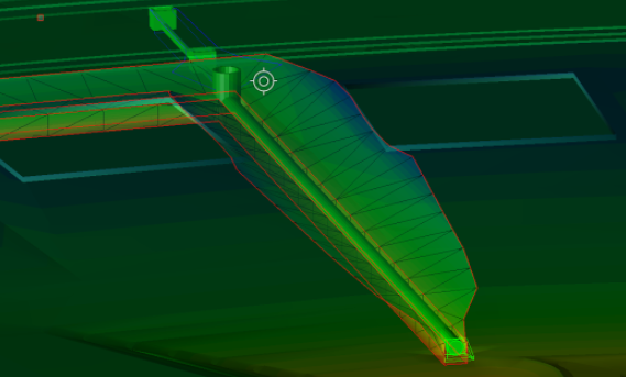
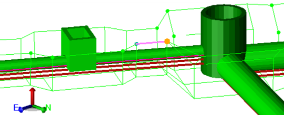
When designing a trench template and inserting it into a run, you can specify to add extra excavation at all nodes, both between the node sides and trench walls and between the node bottom and trench bottom. Since the bottom of a node is typically defined as the invert, you probably need to specify a distance to accommodate the base of the node and any additional excavation to place materials below the node. The image below shows how a node at a bend in a run can be modeled. In addition to the Surface Slicer View, a limit box and the Cutting Plane View can be used to slice through the surfaces and utility lines.
Note: Once a trench surface has been created, you can subsequently remove the utility run as a member of it so you can send it to a field device.
Note: When a utilty run is exported to a project link file (.vcl) the associated trench surface (if created) is included.
Prerequisites:
- Licensed module; See the Subscription Plans page. For a license matrix by command, see the License page in the TBC Community. Also see View and manage licensed features.
- Utility run into which one or more trench templates have been inserted
To access the command:
- Select Create Trench Surface in Utility > Trench.
- Right-click a utility run and select Create Trench Surface.
To create a trench surface:
- In the Utility run list, select the run for which you want to model the trench.
- Click OK. The utility trench surface is created and appears in graphic views and in the Project Explorer under the utility run. A filled trench boundary (the color is specified by the template) and a movable map legend are also created in the Plan View.
To edit a trench surface:
Use the View Filter Manager to hide the surface. Then select and edit the individual linestrings used to form the surface. In properties, you can set the Rebuild method to By user so the surface does not constantly rebuild while you are editing it. Then make the surface visible again.
Dependencies:
- Utility trench surfaces are dependent upon the utility run, trench templates, and target surface from which they are built; if you change any, the changes are reflected when the trench surface is rebuilt.
