Create a Rectangle Using the CAD Command Line
Use the Create Rectangle command alias on the CAD Command Line to draw rectangular polylines using one of two modes: using two opposite corner points or two corner points on one side of the rectangle and then a third point on the opposite side.
Prerequisites:
- License; See the Subscription Plans page. For a license matrix by command, see the License page in the TBC Community. Also see View and manage licensed features.
To create a rectangle from the CAD Command Line:
- Press [F3] or click the
 icon on the Status Bar to open the CAD Command Line.
 - Type rec or REC at the command prompt, and press [Enter].
- If needed, set the Layer, Color, and/or Line style below the command prompt. These properties persist the next time you run the command.
- Based on the Diagonal mode highlighted at the prompt, pick two corner points in a supported view (Plan, Sheet, or Cutting Plane), or enter two coordinates, or enter a keyword character to use another mode. The options are:
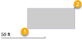
- Diagonal - Enter D, then pick the rectangle's first corner point and the opposite corner point.
- Three point - Enter T, and pick one corner, a second corner on the same side, and then a width. For the width, pick a point on the oppoosite side of the rectangle or enter a positive number to add the width to the right side of the line created from first corner to second corner; enter a negative number to add the width to the left side.
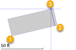
Tip:This mode is useful when working with point clouds where you can use a limit box or cutting plane to specify a cross-section of an object (for example, a building facade) and then select three points to generate a rectangle within the view.
The command remembers the last mode used the next time you run the command.
- Diagonal - Enter D, then pick the rectangle's first corner point and the opposite corner point.
- To create another rectangle, press [Spacebar] to rerun the command.
Dependencies:
- None.
