Create Side Slopes
Use the Create Side Slope command to create a cross-sectional template to be applied along a selected 'master' line so that you can model complex side slope geometery. The template geometry (multiple, lines offset at a given interval from (and dependent upon) the master line) is defined using TBC's Corridor Template Editor.
The linework created by this command can then be tied to one or more surfaces to model scenarios such as levees, curb-and-gutters, above-ground pipe coverage, and other structures where side slopes are needed.
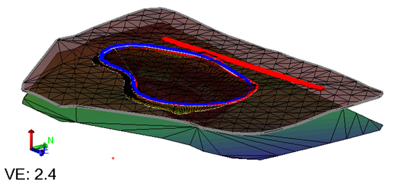
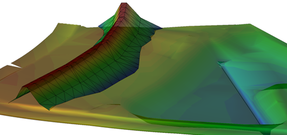
Figure: Side slope along a reference line tied to two surfaces
Note: Unlike the Create Surface Tie command command, the Create Side Slope command can create more sophisticated cross-sectional geometry (see images below).
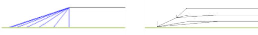
Figure: Side view of simple surface tie versus more complex side slope extending down from top edge of a building pad
Prerequisites:
- Line to use as the master line; basically defining the main path of the side slope
- One or more surfaces to which the sideslope may be tied
- See the Subscription Plans page. For a license matrix by command, see the License page in the TBC Community. Also see View and manage licensed features.
Note: You cannot have a vertical alignment, select more than one reference line, any reference surfaces, or compute areas and volumes of materials with this command. You can, however, use the same templates used for a corridor.
To access the command:
- Select Create Side Slope in Data Prep > Lines.
To create corridor side slopes:
- From the Master line box, pick the line you want to use to offset the sideslope lines from in a graphic view. You may need to create the master line first using one of the commands on the CAD ribbon tab.
- In the Begin station box, enter the station at which to start the offset lines (which will continue to the end of the master line) or pick the station in the view.
- Select an Option for the template definition the side slope will use:
- New definition - Opens the Edit Corridor Template command where you can define a new side slope template.
- Copy definition - Enables you to select an existing side slope template used within your current project.
- From file definition - Allows you to select a previously defined template file stored outside your project.
Tip: Save your side slope and corridor templates for easy and consistent reuse. See Reuse a Corridor Template.
The templates created are the same as the template files created for a corridor.
- Select the layer on which the new side slope object will reside in the Side slope layer list.
- In the Line layer list, select the layer that the new offset lines will be placed.
- Specify a Sampling distance to define the interval between the offset lines.
- Optionally, enter a Template name for the new template that defines the offset side slope lines.
- Click Insert to create the side slope object and place the template at the specified starting position (indicated by the small yellow diamond). The Corridor Template Editor and Edit Corridor Template command open.
- Enter one or more template instructions to define the cross-sectional shape of the side slope, starting with selecting the master line in the ... from list, e.g., Offset/Slope from. Use the Side Slope instruction type to tie your template lines to one or more target surfaces. For more info, press F1 to see any Create ... Instructions help topic.
- As soon as the side slope template is defined, the side slope lines are created in the model. Side slope templates do not appear in the Project Explorer.
- If needed, select the lines and use them to define a surface (side slope lines do not need to be added to a surface if they are already tied to the surface using a side slope template).
Scenarios:
- You can edit the sideslope object and change the master line and optionally add a reference line. The reference line will be displayed in the template editor.
Dependencies:
- If you edit the master line, the dependent lines created from it are updated accordingly. If you delete the master line, the sideslope template and object are deleted (externally saved templates remain).
