Create Side Slope Instructions
The Side Slope node instruction type defines a side slope node based on either or both of the following:
- Cut slope and, optionally, a ditch width
- Fill slope
The side slope node specifies the cut or fill slope intercept with a target surface. For example, the instruction might specify that a node be created that is located at a slope of 2% from the edge of a roadway drainage ditch at the intercept point with the surface, indicating where the surface needs to be cut.
Note: Because of the interdependent nature of template nodes, the instructions used to create the nodes must be in the correct sequence in the Instructions list. For example, you must add a node to the template before you can add another node that references that node for its location. The software builds the template step-by-step based on the sequence of the instructions.
To create a new Side Slope template instruction:
- Display the Edit Corridor Template command pane for the template for which you want to create a new Side Slope instruction as described in Create Corridor Template Instructions.
- If instructions are displayed in the Instructions section located beneath the template view, do the following. Otherwise, proceed to step 3.
- In the Instructions list, select the instruction after or before which you want to insert the new instruction.
- Click the Add Instruction button located at the top of the Edit Corridor Template command pane.
- In the Instruction Type drop-down list, select Side Slope.
- In the Side slope from drop-down list, select the node on which the slope (or ditch width; see step 7) for the new node will be based.
If you select <Previous Node>, the node created by the preceding instruction in the Instructions list is referenced. If there are no preceding instructions in the list, the node automatically created for the horizontal alignment is referenced.
Tip: You can also pick the 'from' node in the graphic pane of the template editor. To make the locations of nodes more obvious, select Options > Show node labels at the bottom of the editor.
- To have the instruction intersect a target material layer (e.g., Finish, etc.) rather than a surface, check the Target material layer box. This changes the choices in the next step.
- Select a target surface (or material layer) by doing one of the following:
- Select the surface (or material layer) in the Target surface drop-down list.
- Click in the Target surface field and select the target surface in the template view or Plan View.
- If you want to specify a cut slope to your target surface, click the Cut slope button and select the appropriate cut slope type:
- Slope percent
 - Enter the percentage of slope from the Side slope from node (or the outer edge of a ditch if one is specified; see step 7) to the new node. Include a minus sign to indicate a negative slope. Or, select the slope in the Plan View (select two points) or template view.
 - Slope ratio
 - Enter the ratio of the slope from the Side slope from node (or the outer edge of a ditch if one is specified; see step 7) to the new node. Or, select the slope ratio in the Plan View (select two points) or template view.
 - Node to node
 - Select the node combination in the drop-down lists that provides the slope you want to use to specify the slope from the Side slope from node (or the outer edge of a ditch if one is specified; see step 7) to the new node. Or, select the nodes in the template view.
 - Table
 - Click the More button to display the Edit Table dialog. Then specify the slope between the Side slope from node (or the outer edge of a ditch if one is specified; see step 7) and the new node at each station in the corridor from the current template to the next template (or the end of the corridor).
 You can type the station in the Station field, or you can select it in the Plan View. You can type the slope value in the Slope field (include a minus sign to indicate a negative slope), or you can select the slope in the Plan View (select two points) or template view.
- Shareable slope table
 - If you have created a shareable slope table for the corridors alignment, you can use this to define the slope at specific stations along the alignment. Select the shareable slope table from the list, or click a shareable slope table line in the Superelevation Diagram.
 - Slope by depth table - Create a table of depth and slope values for a side slope (rather than creating a long list of conditional statements). Enter a Slope, Maximum depth, and Name for each segment in the side slope (enter a negative value (-) when you want the slope to go down). The slope is used up to the indicated depth from the last point; then the next segment is used. This option enables you to create sloped side ditches (as shown in the example below with 4 segments).
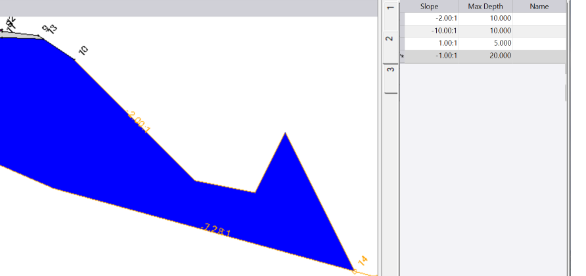
You can create multiple groups of slopes and depths; click New Group at the bottom of the pane to add another group. Group tabs appear on the left side of the table. Each group can have more than one line of slopes and depths so that the tie has multiple segments. When a group has more than one entry, the side slope is formed to the first depth (if it does not intersect the surface first), then the second slope is used, and so on (as shown below).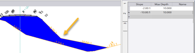
Each group needs to be entered from the smallest depth to the largest so that the program finds the smallest first.Tip: When using a slope by depth table, you can override the default behavior of the intersection stopping at the first intersection with the specified surface. To do this, enter a numeric value for the name of the last intersection. Specify -1 to keep the last intersection. Specify -2 to keep the next to the last intersection. Specify 2 to keep the second intersection.
- Slope percent
- If you want to include a drainage ditch in your side slope, in the Cut ditch width field enter the width for the ditch. The cut slope will be calculated based on the outer edge of the ditch. This field is available only if you enter a Cut slope value.
- If you want to specify a fill slope to your target surface, click the Fill slope button and select the appropriate fill slope type. See step 6 for options.
- Select an option in the Tie direction list:
- Left/Right - Normally the direction is determined by the segment the instruction is tied to, which is typically away from the centerline. This option allows you to control the direction.
- Auto - This option allows the program to determine the direction from the segment the instruction is tied to.
- In the Name drop-down list, select the name you want to use for the new node. Or, type in a new template node name. Selecting or entering a template node name is optional. For additional information, see Create, Edit, and Delete Template Node Names.
- In the Material layers list, check boxes for the material layers on which you want the line segment(s) created by the instruction to appear. Selecting a layer is optional. However, if you do not select a layer, no line segment is created. (Corridor line segments are displayed in the Plan View and 3D View. If you export the corridor, they are used to create the exported corridor surface.) For additional information on material layers, see Understanding Corridor Material Layers and Corridor Surfaces and Create, Edit, and Delete Material Layers.
- If you have any of the boxes for subgrades checked in the Material layers group, the Material above list is enabled. Select a pre-defined material as the material above the instruction that you are editing, or select <New> to open the Material and Site Improvement Manager where you can define materials. If shrinkage, bulkage, or compaction factors have been specified for an earthen material, they will be used in any corridor volume calculations.
Note: The use of material layers requires a license. See the Subscription Plans page. For a license matrix by command, see the License page in the TBC Community. Also see View and manage licensed features.
- Do one of the following:
- Click the Add After buttonto insert the new instruction after the selected instruction in the Instructions list.
- Click the Add Before buttonto insert the new instruction before the selected instruction in the Instructions list.
Note: If there are no instructions in the Instructions list, click either button to insert the new instruction as the first instruction in the list.
The new instruction is inserted into the Instruction list. The new node and line segment are displayed in the template view. The fields are cleared and you can repeat this procedure to create and add more instructions to the template.
Note: Once you have created corridor template instructions for one side of a corridor centerline, you can use the Mirror Instructions command button (located at the top of the Edit Corridor Template pane) to copy them to the other side of the centerline with reversed offsets. This can save you time and help you avoid errors when creating a corridor template. See Mirror Corridor Template Instructions for more information.
Scenarios:
- If you are unable to tie a corridor side slope instruction to the original ground (OG) surface when a transition is required between cut and fill conditions, TBC might be restricting the side slope instruction based on the sign of the slope value relative to the vertical position of the tie-in point. This issue can, for example, occurs in a corridor where the tie-in point is consistently under the OG reference surface (the side slope instruction is only applying a cut slope because the tie-in point is below the OG surface.
Cut slopes are restricted to positive slope values. Using a negative slope value with a cut instruction will not work. To tie the corridor back up to the OG surface when the tie-in point is under the OG, a fill slope is technically required (which uses negative slope values). This restriction prevents the design from handling standard cut-to-fill transitions required by superelevation or varying terrain, as the instruction cannot automatically switch between requiring a positive (cut) and a negative (fill) slope based on the geometry. You are "stuck" and cannot complete the corridor design by tying it to the OG.
When Honor sign of the slope is set to true in Project Settings > Computations > Corridor, negative cut and fill slopes are honored when creating side slopes. Change this setting to true to allow a single side slope instruction to handle the transition from cut to fill (or fll to cut) dynamically, based on the vertical position relative to the OG surface.
