Understanding Corridors and Corridor Surfaces
Typically, you create a corridor based on design information contained in any of the following formats:
- Detailed plots of the horizontal and vertical alignment, typical cross-sections, and callouts describing specific details of the road
- An AutoCAD file with digital representations of the plan
- A corridor in a GENIO file or LandXML file
In Trimble Business Center, a corridor consists of an alignment and one or more cross-sectional templates that can be used to build corridor surfaces, which are 3D models of a linear structure, such as a road or waterway. The alignment (comprised of a horizontal and (optionally) a vertical alignment) defines the path (usually centerline), elevation, and stationing of the corridor. The templates, which control cross-sections throughout the length of the corridor, define the width and shape of the corridor.
A corridor can also reference a surface that represents the existing terrain on which the corridor will be built, as well as other surfaces and reference lines that represent features along the corridor's path.
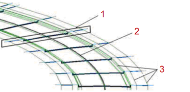
- Cross-sectional template
- Horizontal and vertical alignments
- Reference lines
Figure: Parts of a corridor
Alignments
Corridor templates
After creating a corridor, you insert one or more corridor templates that define what the corridor looks like in cross-section from the station at which the template is inserted until the station at which the next template is inserted, or to the end of the corridor.
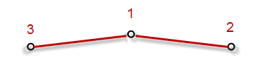
You define the cross-sectional shape of each template using an instruction for each segment of the shape. As a simple example, you might have a 2-lane road that is 8 m (24') wide and slopes from the centerline to each edge at -2% (for drainage). In this case, two instructions are required: one to define the location of the right edge of the pavement (represented by node 2), and one to define the left edge of the pavement (represented by node 3). For these two instructions, the offset and slope are relative to the centerline (represented by node 1).
Of course, you can design much more sophisticated templates that include many types of instructions that use offsets and slopes that are relative to the centerline node, that reference line nodes, and/or nodes resulting from other instructions. You can also associate template instructions with different material layers of the corridor (for example, "Finished", "Base", and "Subgrade") so that you can build and export the various corridor material layers as surfaces.
Reference lines and surfaces
When you reference lines and surfaces with a corridor each line and surface becomes usable as a node to which you can attach instructions in your templates. See Add and Remove Corridor Reference Lines.
Materials
Using the Material above setting for each template instruction, you can specify the materials to be used to build each material layer of the corridor. The materials that you specify do not affect material layers or subsequent corridor surfaces created from the material layers, but do affect the volume calculations displayed for each subgrade in the Corridor Template View.
Material layers and corridor surfaces
Once you have created the corridor and inserted templates, you can build corridor surfaces from the top level surface (finished design) and any other material layers (subgrades) for which you have added instructions. In building each corridor surface, the software connects the templates with linestrings that transition from one template to the next (as shown below) as necessary to create the 3D model. See Understanding Corridor Material Layers and Subgrade Surfaces.
Note: If you open a project with a corridor that was created in a version prior to Trimble Business Center 3.50 or Business Center – HCE 3.30, you must recreate any corridor surfaces that you need.
Corridor intersections and intersection surfaces
Note: Trimble Business Center does not support corridor intersections and cul-de-sacs at this time.
To connect corridors to each, use the Create Intersection command to create parametric geometry for the junction between two or more alignments or corridors. Then you can control the shape of the intersection using properties for the various lines used to form the intersection.
You can also add a roundabout or turning hammer to the dead-end of a corridor using the Create Cul-de-Sac command to create parametric geometry at the end a single alignment or corridor. See Understanding Corridor Intersections and Cul-de-Sacs for more information.
