Calculate Coordinates Using Coordinate Pickers
Use a set of 'coordinate pickers' (coordinate geometry (CoGo) shortcuts) to quickly calculate 3D coordinates/pick points within commands running on the CAD Command Line. The coordinate pickers can be used in all views that support using the CAD Command Line (Plan View, 3D View, Sheet View, Cross-Section View, or Cutting Plane View).
Prerequisites:
- The CAD Command Line is open and running a command that prompts you for a coordinate
- License; See the Subscription Plans page. For a license matrix by command, see the License page in the TBC Community. Also see View and manage licensed features.
To access coordinate pickers on the CAD Command Line:
- Press [F3] to access the CAD Command Line.
- While in a command there, if you need to calculate a coordinate or pick a point, click the Coordinate Picker icon and choose a picker, or simply type one of these shortcuts (an apostrophe and two characters as shown in blue):
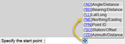
On the command line, you will see >> appear to indicate that you are in the coordinate picking mode. You can press [Esc] any time to exit coordinate picking mode and return to the command.
Note: When specifying the elevation for a coordinate, the >> disappears because you are not in coordinate picking mode, but you are then returned to the mode after the elevation is entered.
The coordinate pickers include:
Angle/Distance
Enter a coordinate using an angle and a distance. You are prompted for two points or a reference line segment on which to base the angle and distance.
- When prompted for a coordinate (or northing/easting), enter 'AD or 'ad on the CAD Command Line.
- Specify the reference angle on which the new angle will be based by picking either two points or a line segment:
- If you pick a line segment, the start point of the line is used as the base point and the angle of the line is used as the reference angle.
- If a line segment is not available/applicable, enter [P] (to use points). Then pick two points to define the angle. The first point is used as the base point and the angle between the points is used as the reference angle. If you have selected two or more points, the reference angle is created from the last two points and the second point (of the three) is the base point.
- Enter an angle as a deflection (180 degrees being straight ahead) from the reference angle.
- Enter a distance from the first point of the reference angle.
- Enter an elevation for the coordinate. The calculated coordinate is entered and you are returned to the command in progress.
Azimuth/Distance
- Enter a coordinate using an azimuth and a distance. You are prompted an anchor point, the azimuth, and a distance.

A. North azimuth system B. South azimuth system
- When prompted for a coordinate (or northing/easting), enter 'ZD or 'zd on the CAD Command Line.
- Pick a start point from which the distance will be calculated.
- Pick a second point to specify the azimuth (measured clockwise; zero is north) or enter an azimuth.
- Enter a distance or pick another point away from the first point to specify it.
- Enter an elevation for the coordinate. The calculated coordinate is entered and you are returned to the command in progress.
Bearing/Distance
Enter a coordinate using a bearing and a distance. You are prompted for a starting point. Then enter a quadrant (1-4/clockwise NE-NW), a bearing, and a distance.

- When prompted for a coordinate (or northing/easting), enter 'BD or 'bd on the CAD Command Line.
- Pick a start point from which the distance will be calculated.
- Enter one of these for the bearing's quadrant:
- 1 NE
- 2 SE
- 3 SW
- 4 NW
- Enter an angle within the quadrant.
- Pick another point away from the first point to specify the distance or enter a distance.
- Enter an elevation for the coordinate. The calculated coordinate is entered and you are returned to the command in progress.
Lat/Long
Enter a coordinate using latitude and longitude values. If your project is in grid coordinates, the lat/long are converted to match the current grid system. If your project does not have a coordinate system defined, you will be prompted to select one before entering coordinates.
Note: Regardless of the view you are working in, when you specify a latitude and longitude, they are always in world coordinate system (WCS) coordinates.
- When prompted for a coordinate (or northing/easting), enter 'LL or 'll on the CAD Command Line.
- Enter the latitude or pick a point to specify it.
- Enter the longitude or pick a point to specify it.
- Enter an elevation for the coordinate. The calculated coordinate is entered and you are returned to the command in progress.
Northing/Easting
Enter a coordinate using northing and easting grid values.
- When prompted for a coordinate (or northing/easting), enter 'NE or 'ne on the CAD Command Line.
- Enter the northing or pick a point to specify it. If you pick the point, you are specifying the easting, so the next step is skipped.
- Enter the easting or pick a point to specify it.
- Enter an elevation for the coordinate. The calculated coordinate is entered and you are returned to the command in progress.
Point ID
- Enter a coordinate using a point name/ID or by picking a point object in the Plan View.
- When prompted for a coordinate (or northing/easting), enter 'PN or 'pn on the CAD Command Line.
- Enter a point ID or pick a point in the graphic view.
- Enter an elevation for the coordinate. The calculated coordinate is entered and you are returned to the command in progress.
Station/Offset
Enter a coordinate using a station along and offset from an alignment. You can also pick a line as the alignment and enter a distance along for the station.
- When prompted for a coordinate (or northing/easting), enter 'SO or 'so on the CAD Command Line.
- Pick the alignment ("station provider") in a graphic view.
The station provider you choose is remembered for the next time you use this coordiate picker, but you can pick a different one if needed. To use the same station provider, the command returns to Enter station. To use a different station provider, press [Esc] to return to the current Station/Offset coordinator picker, and re-enter the Station/Offset mode.
- Enter a station or a point in a graphic view to specify it. If you graphically pick the station in the view, the offset is also specified so you can just press [Enter].
- Enter an offset from the alignment (+ positive to the right side and - negative to the left side of the alignment in direction of ascending stationing) or pick a point away from the alignment to specify the offset.
- Enter an elevation for the coordinate. The calculated coordinate is entered and you are returned to the command in progress.
