View and Edit Level Data
The Level Editor dialog is displayed automatically immediately after you import level data into your proejct. You can also display it any time after import by right-clicking the level data file in the Project Explorer pane and selecting Level Editor from the context menu. The Level Editor dialog enables you to do the following:
- View all level readings from the field, and select any reading to be "enabled" (used for computation of level adjustment) or "disabled" (not used for computation of level adjustment).
- Select which points to import.
- Select to use raw or adjusted elevations in the project.
- View the sums of backsight distances and foresight distances.
- View the total misclosure and individual residuals for benchmarks and coordinates.
- View the elevation type for each point (benchmark, computed, or coordinate), including the start and end points, and change the elevation type as necessary.
- Manually enter benchmark heights and qualities.
- Assign an elevation coordinate already in the project that specifies height and quality that cannot be changed.
- Adjust level runs to spread any misclosure proportionately throughout all the measurements.
- Combine level files.
- Split and merge level runs.
- Specify whether or not to allow a network adjustment to the level data after import (that is, specify whether level data is imported as observations or coordinates).
Before you get started:
Import level data into the project as described in Import DiNi Digital Level Files (.dat), Import Spectra Geospatial Focus DL-15 Files (.l), or Import Level Data Using a Custom Importer.
Prerequisites:
See the Subscription Plans page. For a license matrix by command, see the License page in the TBC Community. Also see View and manage licensed features.
To get started:
- When you import a level data file, the Level Editor dialog automatically displays. Otherwise, you can display it at any time by doing either of the following:
- Right-click the imported level data file you want to view or edit in the Project Explorer and select Level Editor from the context menu.
- Select Level Editor in Survey > Optical. If the Select Leveling Files dialog displays, select the imported level data file you want to view or edit.
The Level Editor dialog displays a tab for each level run in the data file, allowing you to view and/or edit each run individually.
- If no runs display in the Level Editor dialog and/or the Show Bad Runs button is active, click the button to view a list of bad runs that are part of the import data but cannot be imported into your project due to corrupt observations (including negative center-wires, missing end-lines, readings that are not part of a level run, and corrupt stakeouts).
- To delete any run, click the appropriate tab and click the Delete Run button.
- Select any tab whose run you want to view or edit.
At the top of the tab, you can view the sum of backsight distances and foresight distances and the total misclosure to identify issues that might require corrective action.
To select run options:
- At the top of the tab, select the appropriate elevation option:
- Select Use Adjusted Elevations to use elevations in the project that have been adjusted for misclosure. When you select this option, the Correction column is displayed in the table instead of the Misclosure column. The Correction column shows the correction used for the computation of the elevation for each point based on the misclosure value associated with that point.
- Select Use Raw Elevations to use elevations that have not been adjusted. When you select this option, the Misclosure column is displayed in the table instead of the Correction column. The Misclosure column shows the misclosure value for each benchmark or coordinate in the run.
- Optionally, enter a new name for the run in the Run name field.
- Optionally, edit the standard error values displayed in the two Standard error fields.
The default values displayed come from either the Default Standard Errors > Leveling section in the Project Settings dialog or the imported data file, depending on your selection in the Default Standard Errors section in the Project Settings dialog.
Note: If, in the Project Settings dialog, you selected to use standard error values from the imported data file but the file does not contain standard error values, the standard error values entered in the Project Settings dialog are used.
- Standard error per km - This is the standard error on 1 km of double leveling. This value is typically published by the instrument manufacturer.
- Standard error per turn - This is the standard error for each station setup or turning point. This value is typically used when horizontal distances are not known.
If values are displayed in both fields, the standard error value used is the square root of the sum of each of the two calculated values per observation squared.
- In the Show Columns box located in the lower left section of the dialog, select the columns you want to display in the table.
- In the Creation Options box in the lower section of the dialog, select one of the following options:
- Allow Network Adjustment - Select this option if you want all elevations of interest imported as delta elevations and, therefore, adjusted as part of a network adjustment.
- Prevent Further Adjustment - Select this option if you want all elevations of interest imported as control coordinates and, therefore, not adjusted as part of a network adjustment.
- In the Descriptions box in the lower section of the dialog, select one of the following options:
- Create Feature Codes - Select this option if the Description field in the level data file contains feature codes. The feature codes are displayed in the software for the selected observation. You can edit feature codes directly in the Description column.
- Create Field Notes - Select this option if the Description field in the level data file contains field notes. The field notes are represented by nodes beneath the observations in the Project Explorer and can be viewed in the Properties pane. You can edit field notes directly in the Description column.
- Ignored - Select this option if you do not want to import data contained in the Description field in the level data file.
To work with data in the table:
Each station point in the run is displayed in a table, along with the following information about the point (assuming all Columns boxes are checked in the lower left are of the dialog):
- The point ID
- Backsight, foresight, and/or intermediate rod readings associated with the point
- The change in elevation for the point based on the rod reading
- The raw elevation of the point based on the rod reading
- If the Use Adjusted Elevation box is checked, the correction required for the computation of the elevation for the point based on the associated misclosure value
- If the Use Raw Elevations box is checked, the misclosure value for each benchmark or coordinate in the run
- The adjusted elevation
- The type of elevation used for the point: benchmark, coordinate, or computed
- The distance from the instrument to the level rod for each reading
- If applicable, a description entered for a reading associated with the point
- Ensure the boxes in the Create column are checked appropriately.
- Points you want imported into the project (for example, control points) should be checked.
- Points you do not want imported into the project (for example, turning points) should not be checked.
Note: You can select or deselect all of the Create check boxes in the list by clicking the check box located at the top of the column or right-clicking in the column and selecting Include All or Exclude All.
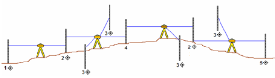
See the following diagram for an example of control points (1, 2, 3, and 5) and a turning point (4).
- Optionally, edit any point IDs in the Point ID column.
If the
 icon displays following a point ID, the point ID is common to multiple runs. This can occur when the surveyor intentionally references the same point in multiple runs, in which case, no correction is required. It can also occur unintentionally when point IDs are automatically assigned in the level device for each run. In this case, you might need to rename one or more of the duplicate point IDs with unique point IDs, as necessary.
 - Ensure the enable/disable boxes in the Backsight, Side Shot, and Foresight columns are checked appropriately.
- Readings you want included in the computation of a level adjustment should be checked (enabled).
- Readings you do not want included in the computation of a level adjustment should not be checked (disabled).
Note: Readings that were aborted in the field are imported as disabled (not checked).
Note: For each point, there must always be at least one backsight reading and one foresight or intermediate reading. Therefore, you can disable a reading for a point only if the point includes additional readings of the same observation type. For example, if a point includes two backsight readings, you can disable one of them, but not both.
- Optionally, in the Elevation Type column change the type of elevation used for any point:
- Benchmark – Select this option to specify that the elevation for the point be a manually entered benchmark elevation. Any point in the run can be designated as a benchmark.
- Coordinate – Select this option to specify that the elevation for the point be a coordinate already assigned to the point in the project. A coordinate can be assigned to a point only if there is a corresponding point already in the project with a coordinate elevation.
- Computed – Select this option to specify that the elevation for the point be computed based on rod readings, benchmark and coordinate elevations entered for the run, and any adjustments performed on the run.
- Optionally, for any points assigned a Benchmark elevation type, do the following:
- Enter or change the value in the Elevation Type column.
- Click the Quality icon and select the appropriate quality option.
- Optionally, enter or change any descriptions in the Description column.
To split level runs:
Optionally, use the various Split Run commands available in the Level Editor dialog to split a single level run into two or three individual level runs. For instructions, see Split Level Runs.
To merge level runs:
Optionally, use the Merge Runs command to merge two level runs displayed in the Level Editor into a single run. The merge requires that the last point ID in the first run selected for the merge matches the first point ID in the second run selected. For example, if the first run selected ends on point 1, the second run selected must start on point 1. If necessary, you can merge another existing run with the newly created merged run using the same guidelines, and repeat as necessary. For instructions, see Merge Level Runs.
To adjust level runs:
Use the Adjust Runs command to adjust one or more level runs displayed in the Level Editor dialog by spreading any misclosure proportionately throughout all of the measurements. For instructions, see Adjust Level Runs.
To complete viewing and editing:
- Repeat the preceding procedures as appropriate for each run you want to view and/or edit.
- When you are done working in the Level Editor dialog, click OK.
If the Level Editor dialog was displayed as part of a data file import, the import process completes and an Import Summary report displays, showing details of the import. Be sure to review any messages, warnings, or errors contained in the report to determine if any corrective action is required.
You can now view keyed-in level data in the Project Explorer.
- To view complete information about the imported level data, including raw observations, reduced observations, and reduced coordinates, select Home > Reports > Level Report.
