View and Interpret a Corridor Mass Haul Diagram
Use the Corridor Mass Haul Diagram command to see:
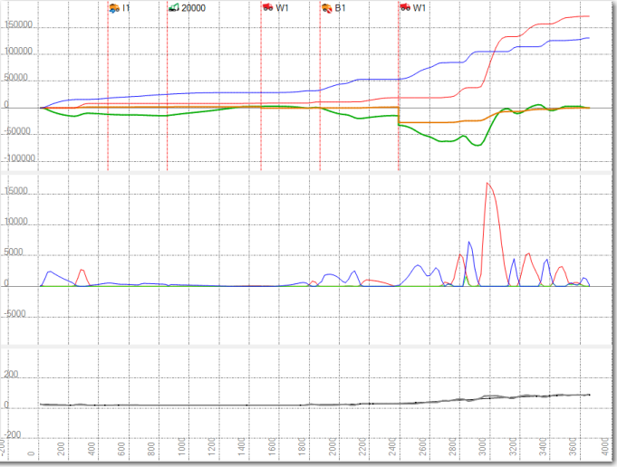
- a mass haul diagram showing accumulated cut and fill volumes (usable and unusable) along a corridor's alignment
- accumulated cut and fill volume for each material
- balance lines and the direction the material needs to be moved
- a graph showing instantaneous cut, fill, and cross haul at each station along a corridor's alignment
- a profile view of the vertical alignment at the same horizontal scale as the Corridor Mass Haul Diagram
The view gives a complete picture of mass haul/earthworks with access to specific mass haul and volume/cost information and cost analysis; this shows the optimal earthwork sites to use based on the lowest cost.
Prerequisites:
- License; See the Subscription Plans page. For a license matrix by command, see the License page in the TBC Community. Also see View and manage licensed features.
- Corridor mass haul analysis
To access the command:
- Select Corridor Mass Haul Diagram in Corrior Mass Haul > Analysis.
- Right-click the mass haul analysis in the Project Explorer (under the corridor name) and select Corridor Mass Haul Diagram from the context menu.
The Corridor Mass Haul Diagram appears, showing the accumulative cut and fill for the corridor.
If the accumulated cut-fill is positive (above zero balance line), then the material is in surplus and needs to be moved forward along the alignment. If the accumulated cut-fill is negative (below the zero balance line) then the material is in deficit and material needs to be moved backwards along the alignment.
When a corridor mass haul is created a sampling distance is specified. This sampling distance determines how the alignment is divided into sections. Cut and fill is determined for each section. For each sampled section:
- If the total cut volume is greater than the total fill volume, the sampled section is 'in cut'. The Usable mass haul ordinate in the mass haul diagram will rise.
- If the total fill volume is greater than the total cut volume, the sampled section is 'in fill'. The Usable mass haul ordinate in the mass haul diagram will fall.
For Corridor Mass Haul:
|
Cut includes the volume of material.. |
Fill includes the volume of material.. |
|
excavated |
required as fill |
|
imported |
exported |
|
borrowed |
wasted |
|
hauled from another section on the alignment |
hauled to another section on the alignment |
|
coming from processing sites |
going to processing sites |
Options:
- Instantaneous graph - Check thisbox to view the amount of cut, fill and cross haul between each sampled section.
- Profile View - Check this box to view the corridor's vertical alignment at the same horizontal scale as the Corridor Mass Haul Diagram.
Note: To view the original surface in the profile view, select Create surface profile in Corridors > Profile.
- Grade points – In the Corridor Mass Haul Analysis' properties, select Points only in the Show grade points box to display points where the graph transitions from 'in cut' to 'in fill' or 'in fill' to 'in cut'. For example: one sampled section is 'in cut' and the next sampled section is 'in fill', this causes the cumulative cut-fill ordinate to begin to fall. The grade point is displayed at the point where the cumulative cut-fill ordinate begins to fall. Select Points and Volumes to display the volumes at the grade points. Grade points are displayed on the material type selected for balancing.
Tip: To change the vertical scale of the Corridor Mass Haul Diagram, press [Control] + [Shift] and roll the mouse wheel.
Mass ordinates:
The mass ordinates displayed in the Corridor Mass Haul Diagram view are determined by the settings in the Mass Ordinate group in the View Filter Manager. You can edit the colors of the mass ordinates by selecting Project > Project Settings > View > Corridor Mass Haul Diagram. The color of a single material ordinate is determined by the color selected for the material in the Material and Site Improvement Manager.
Note: You can edit the color, linestyle and line weight of the mass ordinates in the ordinates properties when your mass haul diagram is ready for plotting. See Preparing a Mass Haul Diagram for Plotting. This setting is not retained when you refresh the mass haul.
Tip: To hide corridor mass haul objects, like imports/exports and barriers, use the Mass Ordinates > General Instances section in the View Filter Manager.
|
Usable Material
|
This line indicates the amount of usable earthwork material (all material types) at a particular point along the corridor. When the Linear Mass Ordinate is above the zero line, the mass haul is in surplus; below the zero line is a deficit. |
| Unusable Material
(orange) |
This line indicates the amount of unusable material (all material types) being carried. In cases where there are no waste sites, unusable material is hauled to the closest start or finish point. |
| "Material name" (Usable) |
This line indicates the amount of a single material (usable) at a particular point along the corridor. When the Linear Mass Ordinate is above the zero line, the material is in surplus; below the zero line is a deficit. The ordinates color is determined by the color selected for the material in the Material and Site Improvement Manager. |
|
"Material name" (Unusable) |
This line indicates the amount of a single material (unusable) being carried along the alignment. In cases where there are no waste sites, unusable material is hauled to the closest start or finish point. The ordinates color is determined by the color selected for the material in the Material and Site Improvement Manager. |
| Cumulative Cut
(red)
|
This line indicates the total accumulated cut at a particular station on the corridor from the start station. |
| Cumulative Fill
(blue) |
This line indicates the total accumulated fill at a particular station on the corridor from the start station. |
Mass ordinates in the instantaneous graph:
| Instantaneous Cut |
This line indicates the amount of earthworks cut (in situ) in a particular station range. |
| Instantaneous Fill |
This line indicates the amount of fill (bank fill) required in a particular station range. |
| "Material name" (Cut) |
This line indicates the amount of a specific material cut (in situ) in a particular station range. |
| Cross Haul |
This line indicates the amount of earthworks moved across the alignment and used as fill in a particular station range. |
Diagram symbols and warnings
In addition to displaying the mass earthworks ordinates, the Mass Haul Diagram indicates warnings, the placement of earthwork sites, barriers, import, and exports, and how each affects the Linear Mass Haul Usable and Unusable ordinates.
To view how the mass haul object is used on the analysis: in the Mass Haul diagram, if the properties pane is displayed click a mass haul object. If the properties pane is not displayed right click the object and select Properties from the context menu.
- Warnings are represented by flag icons
 in the diagram. They represent an imbalance as a result of a surplus or deficit of material occurring at the end of the corridor or at any barrier. Examining the properties for any warning gives details about the actual volume (compacted) of surplus or deficit. A red dashed, vertical line indicates where along the alignment the warning is occurring.
 - Barriers are represented by barrier icons
 in the diagram. To be successfully balanced, the usable mass haul must be balanced between the start and end of the corridor and/or between any barriers along the corridor.
 - Hauled Material is represented by haul icons
 and
and  in the diagram. They show excess material has been hauled along haul roads to other sections of the alignment. This occurs when a barrier has been circumvented using available haul roads or it is less expensive to use the haul roads than it is to move the material along the alignment.
Haul icons display at the station where the haul road meets the alignment. When a haul icon is selected in the diagram the properties for the haul display.
- Export locations are represented by export icons
 in the diagram. They represent the location of a usable material exported from the corridor. A red, dashed, vertical line connecting the icon to the corridor illustrates where export occurs. The Linear Mass Ordinate Usable will change at this location by the volume (compacted) defined in the export.
 - Import locations are represented by import icons
 in the diagram. They represent the location of a material imported to the corridor. A red, dashed, vertical line connecting the icon to the corridor illustrates where import occurs. The Linear Mass Ordinate Usable and Linear Mass Ordinate Unusable will change at this location by the compacted volume defined in the import. If a distribution distance is entered, the usable and unusable mass ordinates will increase gradually over the specified distance.
 - Borrow locations are represented by borrow icons
 in the diagram. This represents where borrow sites are used along the corridor via haul road access. When a borrow location is selected in the diagram, the path of haulage through the defined haul road network is selected in the Plan View, and the properties for the borrow pit displays. The properties of a borrow pit include:
- Name: the name of the borrow site being used
- Capacity: the total capacity of compacted material available at the borrow pit
- Spare Capacity: the amount of compacted material remaining at the borrow pit
- Station: the station value where the borrow instance is used. If the available volume of material and the haul road network permits it, a single borrow pit can be used at multiple locations along the corridor.
- Usage (usable): the volume of usable (compacted) material borrowed from the borrow pit
- Distance: the total distance that material is hauled from the borrow pit to the borrow location on the corridor
- Haul cost: the cost of hauling the specified volume of material from the earthworks site to the corridor. This is based on the specified cost of haul per km/mile on the haul road, the volume of material hauled, and the distance being hauled along the haul road. Haul costs are computed for loose volumes.
- Site cost: the cost of material being used from the borrow pit, based on the volume of (compacted) material multiplied by the unit cost of material
- Total cost: the combined cost of haul and site cost
- Materials: The type of material borrowed.
- Waste locations are represented by waste icons
 in the mass haul diagram. This represents where waste sites are used along the corridor via haul road access onto the corridor. When a waste location is selected in the mass haul diagram the path of haulage through the defined haul road networks is selected in the Plan View and the properties for the waste site display. The properties of a waste site include:
- Name: the name of the waste site being used
- Capacity: the total capacity of the waste site
- Spare Capacity: the amount of capacity remaining at the waste site
- Station: the station where the waste is removed from the corridor. If the available volume of material and the haul road network permits it, a single waste site can be utilized at multiple locations along the corridor.
- Usage (usable): the volume of usable (bank) material being dumped at a waste site at this specific station
- Usage (unusable): the volume of unusable (bank) material at this specific location
- Distance: the total distance that material is being hauled from the waste site to the waste location on the corridor
- Haul cost: the cost of hauling the specified volume of material from the corridor to the earthworks site. This is based on the specified cost of haul per km/mile on the haul road, the volume of material required, and the distance being hauled along the haul road.
- Site cost: the cost of material being dumped at the waste site, based on the volume of material multiplied by the unit cost to dump it.
- Total cost: the combined cost of haul and site cost
- Materials: the type of material and the volume of each type of material being off loaded at the site.
- Processing locations are represented by processing transfer icons in the mass haul diagram. They represent where processing sites connect to the corridor. Material may be transferred to or transferred from a processing site. The material transferred is displayed in the properties pane.
- Processing sites are represented by processing icons at the end of a corridor in the mass haul diagram. When a processing site is selected the material processing that will occur at the site is displayed in the Properties pane. A negative sign indicates the material is used to produce another material. Material with a positive sign indicates it is material that has been produced at the site and is available to be used by the corridor mass haul.
- Site to Site Transfers are represented by processing icons at the end of a corridor in the mass haul diagram. Material is transferred between two sites and does not enter the corridor. When a site to site transfer is selected the material moving from one site to another is displayed in the Properties pane. Site to site transfers occur when
- material at the borrow site is needed by the processing site
- there is excess material at the processing site that needs to wasted.
- a processing site needs material that has been created at another processing site.
- Grade points are represented by blue and red dots. To display grade points view the corridor mass haul properties. In the Show grade points box, select Points only or Points and Volume.
- Balances are shown when a mass haul analysis is balanced, the Corridor Mass Haul Diagram shows:
- Balance lines, with the direction the material is moved
- The amount of overhaul (The remaining volume that has not been balanced)
Plan View
The Plan View illustrates these aspects of the corridor mass haul:
- Borrow sites are represented with the icon.
- Waste sites are represented with the icon.
- Haul roads that are used in the corridor mass haul analysis are shown in red.
- Export sites are shown as red dots.
- Barriers are shown as blue dots.
- Import sites are shown as green dots.
- When a mass haul is balanced, the earthworks footprint for each balance line is shown. Selecting a balance line in the Mass Haul Diagram selects the footprint in the Plan View.
