Understanding Drill Planning for DPS900
Drill planning in Trimble Business Center enables you to:
- Import IREDES files that contain drill plans created in the field
- Modify imported drill plans by adding, removing, and changing drill holes
- Create a variety of drill plans to send to DPS900, a Trimble drilling and piling system for road construction and pit mining; the drill plan helps the DPS900 machine operator navigate to holes (nearest, previous, next, or selected), and then guides him in drilling the holes at the planned orientation, inclination, and depth
- Re-import IREDES files that contain the results of drilling based on a specific drill plan
- Report on the quality of as-drilled holes versus planned drill holes
- Browse planned and as-drilled holes by moving to the next hole, row, or column in a drill hole pattern
Prerequisites
- One or more licenses; See the Subscription Plans page. For a license matrix by command, see the License page in the TBC Community. Also see View and manage licensed features.
Drill Plans
Drill plans are drill hole patterns that you can create manually or have the program generate automatically based on parameters that you specify. The types of drill plans you can create include:
- Manual - This type creates an empty drill plan to which you can add drill holes. When you add drill holes, you can specify coordinates for each or you can create drill holes at the locations of existing objects, such as points. (See Create a Drill Plan Manually.)
- Grid - This type creates a drill plan based on a uniform spacing (rows and columns) of blast holes, which can be constrained by a boundary. The target is a design surface. (See Create a Drill Plan Based on a Grid.)
- Reference line - This type creates a gridded drill plan of blast (and optionally split) holes along and offset from a reference line. This type of drill plan can be constrained between a start and end station and by a boundary. The target is a design surface. (See Create a Drill Plan Based on a Reference Line.)
- Boundary - This type creates a gridded drill plan (hole pattern) within a boundary. Split holes are created (facing perpendicularly inward) along the boundary line and blast holes are created within the bounded area. This drill plan type allows you to drill blast holes to a design surface or to a single benching elevation. The target is a design surface. (See Create a Drill Plan Based on a Boundary.)
- Corridor - This type creates a gridded drill plan of split and blast holes along a corridor design, which can be constrained between a start and end station and by a boundary. More importantly, this type of plan supports benching, which allows you to create successive ledges by drilling split holes one vertical level at a time; one set of drill holes is created for each bench. (See Create a Drill Plan Based on a Corridor.)
Drill plans appear in the Project Explorer. The attributes of a drill plan can be viewed and edited in the Properties pane, after which the plan can be rebuilt.
|
Figure: Parts of drilling |
|
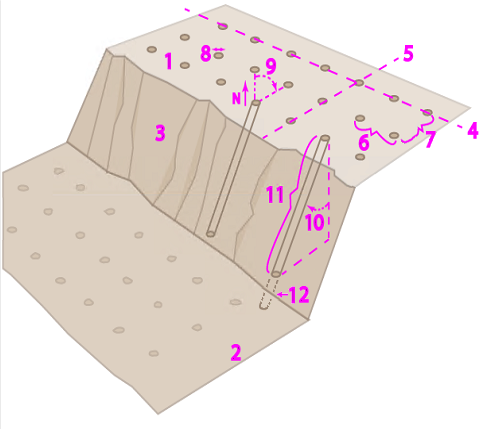
Note: The pattern of the drill plan reflects each drill hole's design point on the targeted design surface. It the drill holes are inclined, that pattern may be different where the holes' vectors intersect with the rock surface and original ground surface based on the topography of each surface. DPS900 assumes that all drill start points are at the current Machine Tool Elevation.
Drill Holes
Each drill plan is composed of individual drill holes arranged in a pattern based on the drill plan's type. Drill hole properties are dependent on parameters specified in each command and in Project Settings. When the settings change after the plan is created, the holes update in graphic views to reflect the changes.
There are three types of drill holes created by a bit:
- Split - This type is drilled in a line (split line) along which rock will be split. The split line is normally inclined inward from the boundary of a blasting area or towards a road centerline. There may be a split line on each side of the road when both sides of the road are in cut. Split holes are narrower, and spaced closer together (along the split line) than blast holes.
- Blast - This type is drilled in a grid pattern within the body of the rock that needs to be fragmented and removed.
- Extra (blast) - This type is a blast hole drilled between the ditch and the split using split subdrilling distance.
- Unknown - This type is given to holes imported in IREDES files for which neither split nor blast has been specified.
All drill holes have these properties: ID, name, diameter, start point, rock point, design point, sub-drilling point, end point, length, and sub-drilling depth.
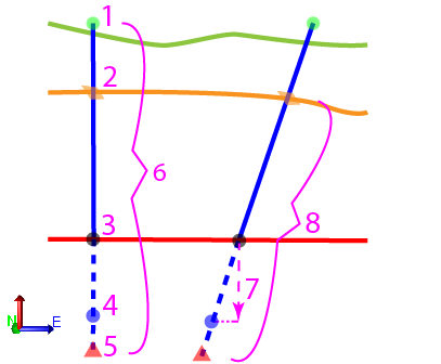
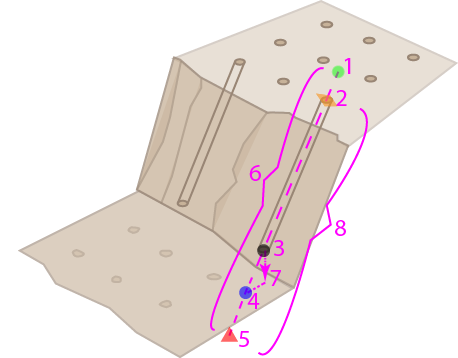
Both vertical and inclined drill holes are stored as vectors, which are shown in graphic views as colored, 3D lines; by default, split holes are red and blast holes are blue (as defined in Project Settings).
Each drill hole's line extends from the start point (allowing for the possibility that the rock surface may not be not known and must be interpolated) through the rock surface to the design point (the target). If there is subdrilling, the hole extends to the end point as well. These points are shown in graphic views as: green (start), orange (intersection with the rock surface), and red (end) circles.
|
Figure: Drill hole elements |
|
Benching
The Boundary and Corridor drill plan types enable you to use benching. Benching allows you to drill split holes in successive vertical levels whereby ledges are created around the edge (once the area is blasted and excavated). Benching may be done to keep the pieces of rock small enough to excavate and haul away. One set of drill holes is created for each bench.
Note: If the rock surface (described below) is unspecified, the split drill pattern cannot accommodate benching. To do benching, all rock surface in one cutting area has to be known.
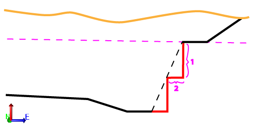
Typically, you will create benches using these parameters:
- Bench height (the standard maximum height for all but the last bench in a sequence)
- Bench width (the width of the flat area) is calculated based on bench height and inclination of the hole
|
Figure: Benching elements |
|
For corridor benching, you need to start drilling further from the centerline of the road to leave room for the benches. The maximum delta height from the road determines the benching. The number of benches needed is calculated upwards from the bottom/design surface. For more information, see bench settings in Drill Plan Settings.
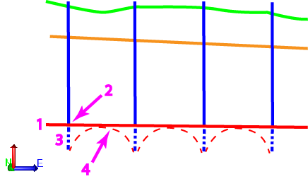
Subdrilling
Subdrilling is the process of drilling below the design so that the resulting surface is on grade after the rock shears; it compensates for the fact that the surface may break unevenly when blasted (as shown in the figure below). The extension of the drill hole beyond the target design point (on the design surface) is also called subdrilling. For more information, see subdrilling settings in Drill Plan Settings.
|
Figure: Subdrilling elements |
|
Subdrilling can be defined by the following parameters:
- Factor of burden (row spacing) - The hole depth needs to be increased in direct relationship to the separation of the rows of holes (the burden value).
- Percentage of drill depth - The hole depth needs to be adjusted based on the depth of the hole being drilled (this is computed on the fly based on the drill start elevation and the target surface elevation at the drill pattern location). The additional drill depth here indicates that a greater depth of hole is required when there is more rock depth to be excavated.
Note: The display of the drill pattern in 2D/3D cannot allow for the Drill Depth percentage because the rock surface is likely unknown at the time of creating the drill plan.
- Distance (blast holes) - This value is a simple additional depth that can be added irrespective of the depth of the holes being drilled, e.g. 0.2m.
- Distance (split holes, line by line) - This value is a simple additional depth that can be added irrespective of the depth of the holes being drilled, e.g. -0.2m.
Note: One or more of the settings above can be used in combination, e.g., you could have a 0.2 addition plus a factor allowance for drill depth and for burden spacing.
Note: Subdrilling is not a standard item in IREDES files.
Surfaces used in drill planning
- Existing ground - This is the surface on which the drilling machine operates, which may or may not be the same as the rock surface, depending on whether the top levels of other materials have been removed.
- Rock - This is the surface/strata on which the drilling of holes typically starts when the topsoil and any soft rock will have been removed, exposing the hard rock that needs to be split or blasted.
- Design or corridor design - This is the surface that a drill plan is trying to achieve. The design is the target design point for each drill hole that lies either on the design surface or a subdrilling depth below that surface.
Importing Drill Plans and Drilling Results
Both Trimble Business Center and DPS900 support standard IREDES drill planning files. You can import files created by drilling machines running DPS900 (if you build a simple drill plan in the field), export drill plans out as Project Link (.vcl) or LandXML (.xml) files, and then re-import them once drilling has been completed in the field (the as-drilled file name must match the exported drill plan's file name).
