To extract point features from a point cloud automatically:
After completing the preparatory steps in Extract Point Features from a Point Cloud, continue with the steps below to extract point features automatically.
- To ensure the highest extraction speed and accuracy, select View Filter Manager in Views > View and in the Point Cloud Region list check to display only the classified point cloud region containing the point features you want to extract.
This step is optional but highly recommended. See step 5 in Extract Point Features from a Point Cloudfor more information.
- Select the Automatic option and do either of the following:
- If you selected an Extraction type other than Generic, click the Extract button.
The progress of the extraction process is displayed in the Status Bar.
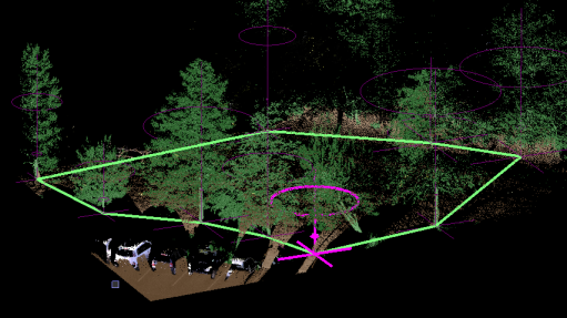
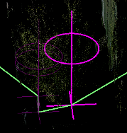
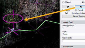
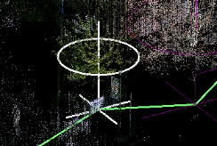
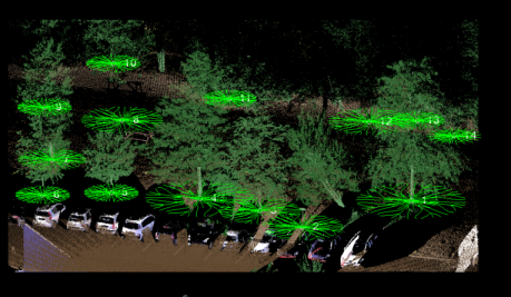
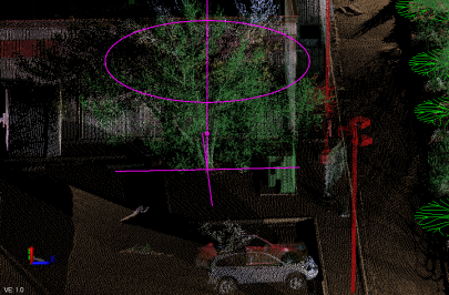
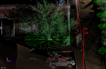
When the extraction process is complete, a green search path displays in the graphic views, and a purple visual extraction indicator displays for each extracted feature. The first extraction indicator is highlighted. (The unselected extraction indicators are dimmed so the that the selection is clearly identified.) Proceed to step 3.
- If you selected Extraction type: Generic:
- Click in the Select point cloud region field and do either of the following to select the points you want to include in the extraction search:
- In a graphic view, draw a box around the points (which may include points from multiple point cloud regions).
- In the Project Explorer, select one or more entire point cloud regions currently displayed in the graphic views.Note: Your selection cannot include more than 20 million points; otherwise, the extraction process will fail and a warning message will be displayed.
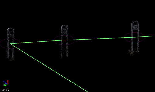
- In the Feature shape drop-down list, select Normal unless the ratio of the width and height of the feature exceeds a 5:1 ratio (for example, a light pole). In this case, select the Vertically elongated or Horizontally elongated option as appropriate, which enables you to apply a scale factor that helps the extraction process correctly identify the cluster of points that defines each feature.
- In the Scale factor for elongated shape field, enter the distance required to best "squeeze" the points that define each elongated feature into a single cluster of points that defines a single feature. (Tip: You may perform the extraction using the default distance, and then change if necessary to improve the results.)
- In the Feature point vertical position drop-down list, select the vertical position of the new feature point within the cluster of points that defines the feature.
- In the Point search radius field, enter the distance around each point within which the extraction process will search for points to include in the cluster of points that define the feature. (Tip: You may perform the extraction using the default distance, and then change if necessary to improve the results.)
- In the Minimum number of radius points field, enter the minimum number of points found within the point search radius that is required for the points to be included in the cluster of points that define the feature. (Tip: You may perform the extraction using the default value, and then change if necessary to improve the results.)
- Click the Extract Point button.
The progress of the extraction process is displayed in the Status Bar.
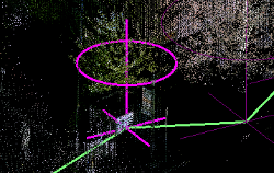
When the extraction process is complete, a green search path displays in the graphic views, and a purple visual extraction indicator displays for each extracted feature.
- Click in the Select point cloud region field and do either of the following to select the points you want to include in the extraction search:
The software attempts to identify and select all of the objects matching the selected Extraction type in the displayed point cloud. But the selection is not always perfect. For example, treeextraction may be difficult if trees are crowded very close together. Therefore, it is important that you review the extracted features to ensure they are correct.
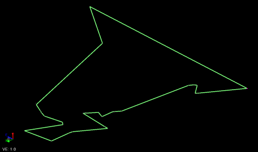
To assist you in reviewing and editing the extracted features in a sequential, systematic manner, a green line is displayed showing a single path that connects all of them. Using the available controls or keyboard shortcuts, you can easily review each of the extracted features along the path and make changes if necessary, as described below.
Feature attributes provided by the extraction process are displayed in the Attributes section on the right side of the Mapped table, along with the values for the selected feature.
You can map feature attributes defined in the project's Feature Definition Library to these extraction attributes to ensure attribution is applied correctly when the new points are created, as described in step 4 below.
- If you selected an Extraction type other than Generic, click the Extract button.
- Optionally, change the displayed Point ID that will be assigned to the first in a sequence of multiple new points.
- If you want to create a point from an extracted feature but do not want to assign a feature code or record feature attributes, ensure no code is entered in the Feature code field for the selected feature as described in the next step, and, optionally, change the layer on which to display the new point in the Layer field.
If you are assigning feature codes (normal workflow) to the extracted features as described in the next step, the feature code itself will determine the layer on which each point is displayed and the Layer control is disabled.
- To assign a feature code and attributes to the selected (highlighted) feature, do the following:
Note: This step includes instructions for mapping extracted feature attributes to corresponding extraction attributes. If you have already imported a Feature Extraction Attribute Map Files (.exl) into your project with appropriate mapping information, you may not need to perform additional mapping as described here. See Import Feature Extraction Attribute Map Files (.exl) and Export Feature Extraction Attribute Map Files (.exl).
- Enter the feature code in the Feature code field. Or, click the Browse button located to the right of the field to make your selection.
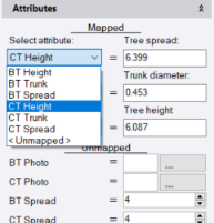
The attributes for the selected Feature code are displayed in the Unmapped section in the Attributes group. If applicable, default values for feature attributes are displayed in the right column. In the following example, the four attributes assigned to the selected feature code are listed. Three of them display the default settings specified for the attributes in the project's Feature Definition Library.
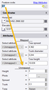
Note: If a feature attribute is required, a yellow circle icon displays next to it. You cannot extract a point feature if a required feature attribute value is not supplied either through a mapped extraction attribute or manual entry.
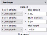
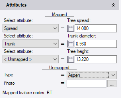
The purpose ofattribute mapping is to specify which feature attribute types defined for the selected feature code in the project's Feature Definition Library match corresponding extracted attribute types. As shown in the example below, attribute mapping can indicate that the tree feature attribute type Spread is the same as the extracted attribute type Tree spread, even though their names are different. This ensures that the extracted value is assigned to the resulting point and displays in the correct Feature Attributes field in the point's Properties pane and in reports.
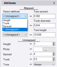
If a feature attribute supports the same data type as an extraction attribute (for example, number, integer, text, file, or other data type), the feature attribute is also displayed in the Select attribute drop-down list located in the left column in the Mapped section
In the following example, the three extraction attributes on the right (Tree spread, Trunk diameter, and Tree height) all support only number values. Two of the feature attributes also support only number values; therefore, these two feature attributes are included in the drop-down list for selection for each of the three extraction attributes. The two non-number attributes (Type and Photo) are not included in the drop-down lists.
Note: Extracted poles and sign features include inclination and inclination direction attributes. The inclination is measured in vertical degrees while the direction is measured in degrees of azimuth or bearing, depending on your Project Settings. This allows you to identify pole and sign features whose inclination exceeds a specified threshold and may, for example, require repairs, without the need to make manual measurements. (The latest GlobalFeatures.fxl feature library file included with TBC includes inclination attributes.)
- To map attribute types for the selected feature code to extraction attribute types, do either of the following. (Both options provide the same results, so feel free to select the option with which you are most comfortable.)
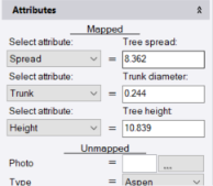
- For each extraction attribute type displayed in the right column in the Mapped section, select the matching feature attribute type in the Select attribute drop-down list located in the left column. If no feature attribute type is available to map to the extraction attribute type, select <Undefined>.
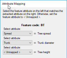
- Click the Map Attributes link located above the Feature code field to display the Attribute Mapping dialog. Then, for each extraction attribute type displayed to the right of a corresponding Select attribute drop-down list, select the matching feature attribute type in the drop-down list. If no feature attribute type is available to map to the extraction attribute type, select <Undefined>. When you are done, click Save.
- For each extraction attribute type displayed in the right column in the Mapped section, select the matching feature attribute type in the Select attribute drop-down list located in the left column. If no feature attribute type is available to map to the extraction attribute type, select <Undefined>.
- Optionally, if you want to assign more than one feature code to the selected extracted feature, in the Feature code field, type a space and enter the second feature code. Or, click the Browse button located to the right of the field to make your selection. Then map attributes for the new feature code as described above.
The first feature code or feature code combination you assign is the default assigned to all of the extracted features. However, you can navigate to any extracted feature as described in the next step and select to assign a different feature code or feature code combination (whose attributes must be mapped as described above the first time it is assigned). This is helpful if, for example, you are extracting tree features to which you want to assign various tree type feature codes. Or, you can select not to enter a feature code at all, in which case you should verify that the resulting point will be displayed on the correct layer in your project using the Layer drop-down list.
Note: You can save your mapping in a Feature Extraction Attribute Map (.exl) file that can be shared with other users and opened in other projects. (See Export Feature Extraction Attribute Map Files (.exl) and Import Feature Extraction Attribute Map Files (.exl).)
- Enter the feature code in the Feature code field. Or, click the Browse button located to the right of the field to make your selection.
- To review and, optionally, edit the extracted point features, do any or all of the following as necessary.
Note: When you select an extracted feature using one of the methods described below, you have the option to change the feature code assigned to it, assign additional feature codes, or assign no feature code, all of which are described in the previous step.
- To view and edit any of the extraction selections independently, simply navigate to the selection in a graphic view and click on it.
- To view each of the extraction selections in sequence along the green selection path, click the Next or Previous button to highlight the next or previous selection. Or, press the Ctrl + Left Arrow or Ctrl + Right Arrow keys.
Note: To display and hide the green extraction selection path, click the Path button
 . Or, press the Ctrl + 0 (numeric keypad) keys.
 - To change the status of the highlighted extracted feature, select one of the following options. Or, press the Ctrl + Up Arrow or Ctrl + Down Arrow keys to toggle between the options.
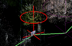
Ignore - Select this option to display the selection in red, indicating it will be ignored during the actual extraction process.
Mark - Select this option to display the selection in white simply as a visual indicator. For example, you may want to mark the selection to be revisited at a later time or to indicate where you started or ended your review.
Normal Select this option to remove a Mark or Ignore option for a selection and display it in its Normal default color purple.
- To display or hide a customizable limit box around the selection in the active graphic view, click the Limit Box button
 . Or, press the Ctrl + Space keys.
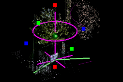
By using the limit box to isolate the selection from its surroundings in the 3D View, you might find it easier to verify the selection is correct. This can be especially helpful when, for example, you are extracting tree point features and multiple trees and bushes are clustered closely together. For instructions on using the limit box, see Limit the Graphic View.
- To move a selection horizontally or vertically, click in the Horizontal or Vertical field and select a new location for the selection. Or, type in a new coordinate.
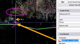
Note that the Horizontal coordinate display order (for example, Easting, Northing) is determined by the Display order setting in Project Settings > Units > Coordinate. You can change if necessary.
Optionally, click the Coordinate Quality button located to the right of each of the two coordinate fields to change the quality of the new point's coordinate.
- To change an attribute value for the selection, click in the attribute field that you want to edit and make changes as necessary. If it is a distance value, click to measure a new distance in the graphic view, or type in a new value.
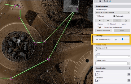
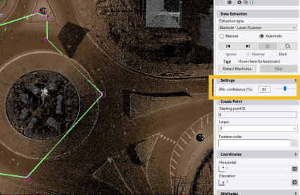
- When extracting manholes, optionally use the Minimum confidence slider control to obtain better results by increasing or decreasing the number of selected manholes.
By default, the minimum confidence is set to 50%, which means there is a 50% likelihood that the manhole exists at the specified location. This confidence level is an optimal compromise between a high detection rate and a low number of false positives. Lowering the confidence level might increase the detection rate, but at the same time it might increase the number of false positives. Increasing the minimum confidence has an opposite effect.
- If you find a feature object that was not found by the extraction selection process (that is, there is no extraction indicator on the object), you can select the Manual option, make your selection, and then re-select the Automatic option to continue your review where you left off.
- If necessary, provide a value for any unmapped feature attributes that include a yellow Required icon.
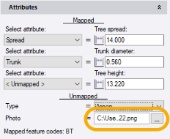
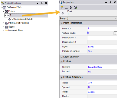
In the following example, the user merely clicked on the Type drop-down list to keep the default Aspen selection and remove the Required icon. The user could just as easily have selected a different tree type in the list.
- Optionally, provide a value for any unmapped feature attributes that are not required.
In the following example, the user has selected a file path for a photo associated with the feature, even though it is not required.
- To view and edit any of the extraction selections independently, simply navigate to the selection in a graphic view and click on it.
- When you are done reviewing all of the extracted features and making edits as necessary, click the Add button or press the Enter key to create the new points.
- If the Projection Definition dialog displays, make changes if necessary and click OK.
The associated feature symbol displays (if assigned) with each new point in the graphic views.
In addition, the new points are displayed in the Project Explorer. Editable feature attributes are displayed for each point in its Properties pane.
- Optionally, follow these steps to further verify the extracted points are correct and, if any are not, fix the problem immediately:
- Ensure that the feature code(s) for the extracted point features you want to verify is/are still selected in the Feature code field
- At the top of the Extract Point Feature command pane, select the Manual option.
- Click in the Pick a point field.
- Press the Ctrl+Down Arrow key to automatically select in sequence each of the point features in your project with the specified feature code(s) to view its accuracy in the 3D View.
Each time you press Ctrl+Down Arrow, the next point feature in the sequence is displayed in the Point ID field in the Extract Point Feature command pane and in the Points list in the Project Explorer. In addition, the point and its associated feature symbol are highlighted and centered in the currently active view.
Optionally, press Ctrl+Up Arrow to select points in the opposite sequence.
When using the 3D View to verify extracted point features, be sure to change the zoom and perspective as necessary to best determine the accuracy of the point's position in relation to its associated feature.
This provides a systematic means of quickly and efficiently viewing each and every point feature with the specified feature code without the need to search them out in the graphic view or Project Explorer, possibly resulting in losing track of what you have and haven't viewed and/or viewing the same point feature multiple times.
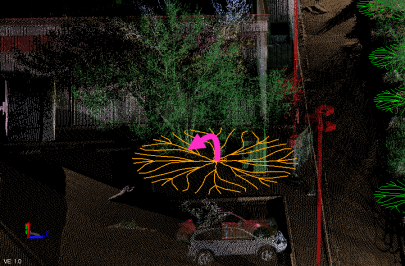
In the following example, a point was created automatically too far from the trunk of its associated tree feature. This was probably due to the fact the the there was a larger spread on one side of the tree trunk than on the other, causing the trunk location to be miscalculated.
- If a selected point is not properly positioned beneath its associated feature or it is incorrect in some other way, press Ctrl+D to delete it.
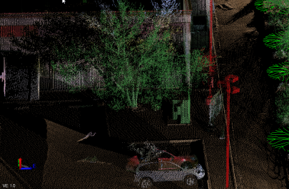
- To manually add a new point feature (either to replace one you just deleted or to create a new one where none existed), do the following:
- Ensure your cursor is in the Pick a point field and then pick the feature in the 3D View.
- Press the Enter key (or click the Extract button) and verify the selection results. Make changes if necessary.
- Optionally change the Point ID for the new point.
- Click the Add button or press the Enter key to save your changes.
Optionally, you can modify or add missing attribute values for any newly created feature point in the point's Properties pane.
