To extract point features from a point cloud manually:
After completing the preparatory steps in Extract Point Features from a Point Cloud, continue with the steps below to extract point features manually:
- Select the Manual option.
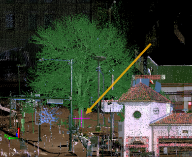
- Click in the Pick a point field. Then, in the 3D View, select a scan point on the object (feature) for which you want to create a feature point.
Due to the nature of point clouds, you may need to rotate the 3D View slightly to be sure that you have actually selected a point on the feature, not a point that is in front of or behind it.
Where you select on the feature depends on the extraction type and is described in the selection field label. For example, for a Tree extraction type, the label is Pick a tree trunk point. However, for some objects it is not always possible to do exactly as the label instructs. For example, the trunk for the tree you want to select might not be visible. In these situations, try selecting a point near the center of the object when viewed in the Plan View or when viewed from above in the 3D View.
Note: When extracting manhole point features you do not have to click on the center of the manhole. You can click anywhere on the manhole and the center and diameter will be automatically calculated.
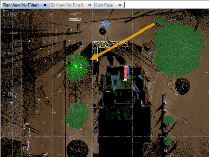
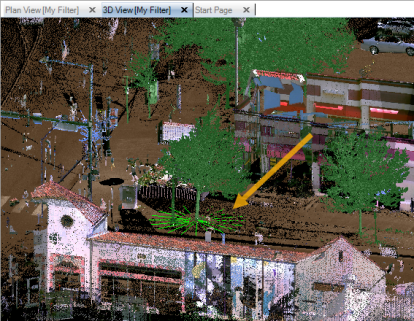
A visual extraction indicator displays on the feature you selected, verifying your selection.
Note: You can also make your selection using a Station View(if applicable). If referenced photo images are included, you can check the Virtual DR check box on the Station View tab to display the
 Pixel Picker, which enables you to select on a referenced photo image the location (pixel) on the feature you want to select. TBC then projects a nearby scan point onto the line-of-sight ray to help calculate the 3D position of the selection. If there are no nearby scan points, an appropriate error message is displayed and you will need to make a new selection. Note that before using the Virtual DR feature, it is highly recommended that you register the scans in your project.
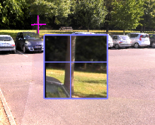
- Click the Extract button, or press the Enter key.
The progress of the extraction process is displayed in the Status Bar.
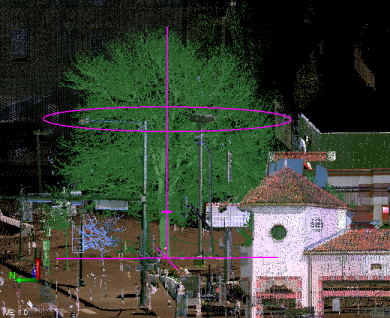
When the extraction process is complete, feature attributes provided by the extraction process are displayed in the Attributes section on the right side of the Mapped table, along with the values for the selected feature..
A visual extraction indicator displays in the Plan View and 3D View for the selected feature. The visual indicator, along with the values displayed in the Mapped section of the Attributes group, provides the feedback you need to verify that the extraction was accurate.
Note:For the highest productivity when using the Manual extraction method, it is recommended that you extract the same types of features in groups so that you are not constantly changing feature codes. For example, extract all broadleaf trees, then extract all coniferous trees, then extract all poles, and so on. This allows for a streamlined workflow in which, once the feature code has been selected and its attributes mapped, you can simply select a feature, press the Enter key once to extract attributes (same as clicking the Extract Attributes button), press the Enter key a second time to add the new point (same as clicking the Add button), and repeat until you have extracted all of the point features for the specified feature code. Then you can select the next feature code and repeat.
- Optionally, change the displayed Point ID that will be assigned to the new point.
The point ID will automatically increment as each subsequent point feature is extracted, unless you change it.
- If you want to create a point from an extracted feature but do not want to assign a feature code or record feature attributes, ensure no code is entered in the Feature code field for the selected feature and, optionally, change the layer on which to display the new point in the Layer field.
If you are assigning one or more feature codes (normal workflow) to the extracted feature as described in the next step, the feature code itself will determine the layer on which each point is displayed and the Layer control is disabled.
- To assign a feature code and attributes to the selected feature, do the following:
Note: This step includes instructions for mapping extracted feature attributes to corresponding extraction attributes. If you have already imported a Feature Extraction Attribute Map Files (.exl) into your project with appropriate mapping information, you may not need to perform additional mapping as described here. See Import Feature Extraction Attribute Map Files (.exl) and Export Feature Extraction Attribute Map Files (.exl).
- Enter the feature code in the Feature code field. Or, click the Browse button located to the right of the field to make your selection.
The attributes for the selected Feature code are displayed in the Unmapped section in the Attributes group. If applicable, default values for feature attributes are displayed in the right column. In the following example, the four attributes assigned to the selected feature code are listed. Three of them display the default settings specified for the attributes in the project's Feature Definition Library.
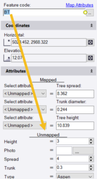
Note: If a feature attribute is required, a yellow circle icon displays next to it. You cannot extract a point feature if a required feature attribute value is not supplied either through a mapped extraction attribute or manual entry.
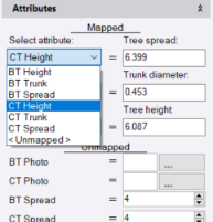
The purpose ofattribute mapping is to specify which feature attribute types defined for the selected feature code in the project's Feature Definition Library match corresponding extracted attribute types. As shown in the example below, attribute mapping can indicate that the tree feature attribute type Spread is the same as the extracted attribute type Tree spread, even though their names are different. This ensures that the extracted value is assigned to the resulting point and displays in the correct Feature Attributes field in the point's Properties pane and in reports.
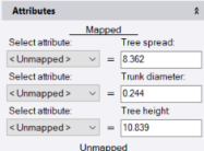
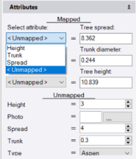
If a feature attribute supports the same data type as an extraction attribute (for example, number, integer, text, file, or other data type), the feature attribute is also displayed in the Select attribute drop-down list located in the left column in the Mapped section
In the following example, the three extraction attributes on the right (Tree spread, Trunk diameter, and Tree height) all support only number values. Two of the feature attributes also support only number values; therefore, these two feature attributes are included in the drop-down list for selection for each of the three extraction attributes. The two non-number attributes (Type and Photo) are not included in the drop-down lists.
Note: Extracted poles and sign features include inclination and inclination direction attributes. The inclination is measured in vertical degrees while the direction is measured in degrees of azimuth or bearing, depending on your Project Settings. This allows you to identify pole and sign features whose inclination exceeds a specified threshold and may, for example, require repairs, without the need to make manual measurements. (The latest GlobalFeatures.fxl feature library file included with TBC includes inclination attributes.)
- To map attribute types for the selected feature code to extraction attribute types, do either of the following. (Both options provide the same results, so feel free to select the option with which you are most comfortable.)
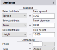
- For each extraction type attribute displayed in the right column in the Mapped section, select the matching feature code attribute type in the Select attribute drop-down list located in the left column. If no Feature code attribute type is available to map to the Extraction type attribute, select <Undefined>.
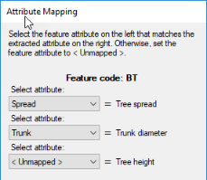
- Click the Map Attributes link located above the Feature code field to display the Attribute Mapping dialog. Then, for each extraction attribute type displayed to the right of a corresponding Select attribute drop-down list, select the matching feature attribute type in the drop-down list. If no feature attribute type is available to map to the extraction attribute type, select <Undefined>. When you are done, click Save.
- For each extraction type attribute displayed in the right column in the Mapped section, select the matching feature code attribute type in the Select attribute drop-down list located in the left column. If no Feature code attribute type is available to map to the Extraction type attribute, select <Undefined>.
- Optionally, if you want to assign more than one feature code to the selected extracted feature, in the Feature code field, type a space and enter the second feature code. Or, click the Browse button located to the right of the field to make your selection. Then map attributes for the new feature code as described above.
The first feature code or feature code combination you assign to an extracted feature when using the Extract Point Feature command becomes the default feature code assigned to each subsequent feature you extract, until you change it.
Note: You can save your mapping in a Feature Extraction Attribute Map (.exl) file that can be shared with other users and opened in other projects. (See Export Feature Extraction Attribute Map Files (.exl) and Import Feature Extraction Attribute Map Files (.exl).)
- Enter the feature code in the Feature code field. Or, click the Browse button located to the right of the field to make your selection.
- Optionally, change any of the extracted values displayed in the extraction attribute fields.
This can be helpful if, or example, the feature was partially hidden and could not be measured accurately—and you know the correct values to enter.
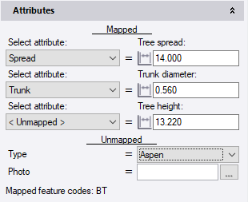
- Provide a value for any unmapped feature attributes that include a yellow Required icon.
In the following example, the user merely clicked on the Type drop-down list to keep the default Aspen selection and remove the Required icon. The user could just as easily have selected a different tree type in the list.
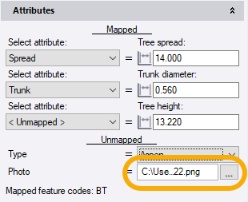
- Optionally, provide a value for any unmapped feature attributes that are not required.
In the following example, the user has selected a file path for a photo associated with the feature, even though it is not required.
Note: Once you have mapped feature attributes to extraction attributes for a feature code, the mapping persists in your project until you change it. That means that each time you select the feature code, the mapped feature attributes are automatically selected by default in the Select attribute drop-down lists. In addition, you can save your mapping in a Feature Extraction Attribute Map (.exl) file that can be shared with other users and opened in other projects. (See Export Feature Extraction Attribute Map Files (.exl) and Import Feature Extraction Attribute Map Files (.exl).)
- Optionally, make changes to the position parameters displayed in the Coordinates fields.
The Coordinates fields, especially when used in conjunction with the Plan View, allow you to "fine tune" the horizontal location of the new point.
The Horizontal coordinate display order (for example, Easting, Northing) is determined by the Display order setting in Project Settings > Units > Coordinate. You can change if necessary.
Optionally, click the Coordinate Quality button located to the right of each of the two coordinate fields to change the quality of the new point coordinate.
- Click the Add button.
- If the Projection Definition dialog displays, make changes if necessary and click OK.
The associated feature symbol displays with the new point in the graphic views.
In addition, the new point is displayed in the Project Explorer. Editable feature attributes are displayed for the point in its Properties pane.
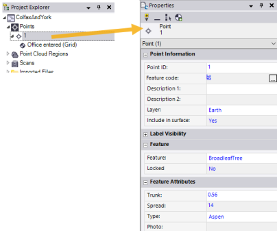
Optionally, you can modify or add missing attribute values for any newly created point feature in the point's Properties pane.
