Measure Values Between Points
Calculate and report values between points in your project.
- In a Plan View, measure the bearing and distance.
- In a Profile View, measure the delta station, slope, and slope distance.
- In a Cross-section and Surface Slicer View, measure the delta offset, slope, and slope distance.
- In a 3D View and Station View (with scan points and Virtual DR activated), measure the bearing, distance, delta vertical, slope, and slope distance.
Prerequisites:
- None
To measure values between two points:
- Select Measure Distance in Home > Data to display the Measure Distance command pane.
- Select one of the following measurement methods:
- Two Points - Calculates values between two points.
- Sequential - Calculates cumulative values between more than two points.
- Radial - Calculates values repeatedly from one point to multiple other points.
- If you are measuring points using a Station View with scan points, check the Virtual DR check box located at the bottom of the tab.
This allows you to use the Pixel Picker to select on a referenced photo image the location (pixel) where you want to create a measurement point. TBC then projects a nearby scan point onto the line-of-sight ray to help calculate the 3D position of the new point. If there are no nearby scan points, an appropriate error message is displayed and you will need to make a new selection.
 More about using the Pixel Picker...
Note: Before using the Virtual DR feature, it is highly recommended that you register the scans in your project. Once the scans are registered, you can select to view all of the scan points in the project on any Station View tab and TBC can then use any of them for the Virtual DR measurement. Just click the View Filter icon located at the bottom of the tab and check the Show scans for other stations check box.
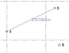
- Click in the From field, and then either click the "from" point in a graphic view or type a point ID (name) or coordinate (Plan View only; use the format X,Y) in the field.
Note: A measurement (length) of the line segment is displayed next to the cursor. The line length is also displayed in the status bar.
When an object is snapped, the distance to the snapped object is displayed next to the cursor.
Toggle this feature on and off using the Show line length preview checkbos in Options > Display.
You can pick either a named survey or CAD point, or an unnamed scan point. If the Free option is checked in the Snap Mode dialog and you are making your selection on the Plan View tab, you can also pick a location where there is no point (not applicable on a 3D View or Station View tab). In this case, only 2D inverse values are calculated.
Optionally, click the Show Snap Options icon located on the command pane toolbar to help make your selection.
You can also right-click in the view to access COGO controls and snaps when picking points.
- Pick a second point or type a point ID or coordinate (Plan View only) in the To field.
The measurement results are displayed in the Results section of the pane.
- To measure additional values, continue picking To points.
As you make each subsequent measurement, the measurement results are displayed in the Results section and in the History section of the command, where all measurements are displayed until you close the project. You can clear the history at any time by clicking the Clear History icon located on the command pane toolbar.
Note the following:
- In the Cross-section View, the slope is relative to the alignment centerline. In the Surface Slicer View, the slope is relative to the first point of the line.
- In the Cross-section View, the offset is relative to the centerline. In the Surface Slicer View, the offset is relative to the first point of the line.
- To save (store in the project) the current measurement displayed in the Results section, do the following:
- Click the Save button.
- In the Save Measurement dialog, optionally enter a new Name for the measurement and/or change the Layer or Color for its display.
If the measurement type is Distance, select the measurement value you want to display in the graphic views by default: Slope Distance, Horizontal, Vertical, Azimuth, or Slope. (You can change the displayed measurement after saving in the stored measurement's Properties pane as described below.)
If the measurement type is Sequence, optionally check the Horizontal measure check box to specify to display the horizontal distance; otherwise the slope distance is displayed.
- Click the Save button in the Save Distance Measurement dialog.
The stored measurement continues to display in the graphic views, even if you make additional measurements or close the Measure Distance command pane altogether.
Note: To specify whether stored measurements are displayed and/or are selectable in graphic views, select View Filter Manager > Advanced View Filter Settings.
Each stored measurement is represented in the Project Explorer by a new Distance or Sequence node nested beneath the Store Measurements parent node. You can right-click any stored measurement node and select Properties to view it in the Properties pane, where you can change the name, layer, and/or color. You can also specify which measurement is displayed in graphic views: Slope Distance, Horizontal, Vertical, Azimuth, or Slope.
If the stored measurement is a sequence distance, you can change whether the measurement is horizontal distance or slope distance..
To delete a stored measurement, right-click it in the Project Explorer and select Delete.
- When you are done, click in the command pane.
