Create Surface Instructions
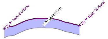
Use the Surface instruction type to create a corridor from an existing surface when you need to compare corridors for earthwork volume calculations. The Surface instruction type defines a single instruction that is derived from the surface it is mirroring. This instruction is unique because it includes nodes at either end that represent the edges of the surface from which it was derived. These nodes are labeled 2L and 2R for the left and right edges, respectively; node 1 is at the centerline. Other types of instructions can be appended to either edge node to modify the template.
Warning: The corridor surface created using this instruction type is not as accurate as the original surface because it only samples the surfaces at each template. Points between templates are not considered when you make a surface. Generally, only the original surface (not the resulting corridor) is accurate enough to be used for earthwork volume calculations or to stake and build a surface in the field.
Note: Because of the interdependent nature of template nodes, the instructions used to create the nodes must be in the correct sequence in the Instructions list. For example, you must add a node to the template before you can add another node that references that node for its location. The software builds the template step-by-step based on the sequence of the instructions.
Note: Also see step 4 and its notes below; the setting enables you to create the instructions from one surface, but clip the extands on yet another, different surface.
Prerequisites:
- Surface
- Corridor
To create a new Surface template instruction:
- Select a corridor and insert a template at a location to open the Edit Corridor Template command for which you want to create a new Surface instruction (as described in Create Corridor Template Instructions).
- Select Surface in the Instruction Type list.
- Select the surface on which you want to base a corridor in the Surface list. This can be any surface, including one that is referenced by the corridor as the Original ground surface.
- If you have two overlapping surfaces from which you want to create the surface instruction, choose a clipping option in the Clip to surface list. This alows you to pick one surface to create the instructions from, but clip the extents based on another, different surface.
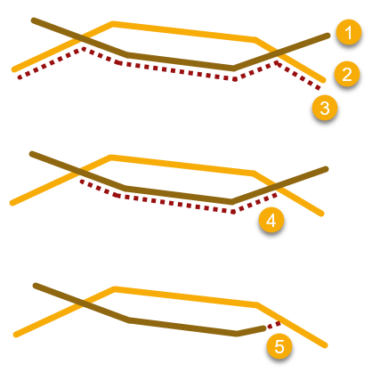
- Trim/extend ends - Trim or extend the instructions (5) to the nearest intersection with the selected surface. Use this to fix small gaps between the instruction and the original surface's extents for the purpose of calculating end areas for volumes. This is not intended to fix large gaps
- Clip above reference surface - Limit the extents of the extracted instruction (4) based on the edge of the upper surface (2).
- Clip below reference surface - Limit the extents of the extracted instruction (3) based on the edge of the lower surface (1).
- Specify a distance that you want to vertically offset the corridor template from the original surface in the Vertical offset box.
Tip: Creating multiple Surface instructions with different vertical offsets in the same template is an easy way to create separate subgrade surfaces for a corridor.
- To prevent instructions being auto-generated at every transition point the program identifies check the Add stations at surface vertices box. Generally, use this only when the surface came from cross sections; otherwise you will have too many instructions/cross-sections.
- To restrict the width of the template, check the Limit extents box; if you choose not to, skip the next step.
- Specify the lateral extents of the template by typing offset values in the Left and Right boxes, or click the
 icon and select an alternate method for entering the extents:
Note: By default, the corridor template extends to the width of the surface it is mirroring. If that surface is wider than the default limit set in Project Settings > View > Corridor Template View > Left and Right extension, then the default will be used to limit the corridor template. The lateral extents of the template can always be adjusted in the Properties pane for the cross-section of the corridor.
Tip: In corridor surface instructions, you can also track from right to left; this allows the Previous node to be on the left.
Note: Since the alignment itself denotes a zero offset, typically the left offset value will be a negative number.- Offset - Enter the offset distance between the centerline node and the new surface edge node. Include a minus sign to indicate an offset to the left of the centerline node. Or, click in the Plan View or template view to select the offset distance.
- Node to node
 - Select the node combination in the drop-down lists that provides the distance you want to use for the offset between the centerline node and the new surface edge node. Or, select the nodes in the template view.
 - Table
 - Click the More button to display the Edit Table dialog. Then specify the offset between the centerline node and the new surface edge node at each station in the corridor from the current template to the next template (or the end of the corridor). You can type the station in the Station field, or you can select it in the Plan View.
In the Offset field, click the button to select between entering an offset distance or referencing a 2D line for the offset. If you select to enter an offset distance, you can either type in the distance or select it in the Plan View or template view. If you opt to reference a 2D line, you can select the line in the Plan View or select the node representing the line in the template view.
- 2D line
 - Click in the field next to the Offset button. Then, select the line on which you want to base the offset in the Plan View, or select the node representing the line in the template view. The new node will use the same offset from the centerline node as does the 2D line.
- Offset
- In the Material layers list, check boxes for the material layers on which you want the instruction to appear. Selecting a layer is optional. However, if you do not select a layer, no line segment is created. (Corridor line segments are displayed in the Plan View and 3D View. If you export the corridor, they are used to create the exported corridor surface.) For additional information on material layers, see Understanding Corridor Material Layers and Corridor Surfaces and Create, Edit, and Delete Material Layers.
- If you have any of the boxes for subgrades checked in the Material layers group, the Material above list is enabled. Select a pre-defined material as the material above the instruction that you are editing, or select <New> to open the Material and Site Improvement Manager where you can define materials. If shrinkage, bulkage, or compaction factors have been specified for an earthen material, they will be used in any corridor volume calculations.
Note: The use of material layers requires a license. See the Subscription Plans page. For a license matrix by command, see the License page in the TBC Community. Also see View and manage licensed features.
- Click Save. The new instruction is inserted into the Instruction list. The new node and line segment (if created) are displayed in the template view. The fields are cleared and you can repeat this procedure to create and add more instructions to the template.
Scenarios:
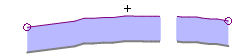
- If the surface that is being referenced has a hole, the template still only creates edge nodes at the outer extents.
Dependencies:
- The corridor template based on a surface instruction is a dependent object; it will dynamically update in response to edits made to the surface from which it was created.
