Create and Edit a Utility Node
Use the Create Utility Node command to create objects such as manholes, headwalls, and junction boxes at the ends or junctions of pipes or cables in a utility network. Typically, creating nodes and pipes individually (where invert elevations are critical) is part of a more careful, manual approach for building gravity networks (as opposed to pressure networks in which pipes and nodes are created automatically). You will probably want to start with plans from a designer for gravity networks. Plans should include coordinates/locations of manholes and headwalls, diameters and types of pipes (in plan and profile), and elevations of pipes at junctions. As you create it, the network can be viewed in the Plan View and 3D View, as well as in the Project Explorer.
Note: The typical workflow for a gravity network is to create nodes at the correct locations first, and then create pipes between the nodes second.
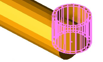
Figure: Schematic block representing a manhole
Tip: You may want to open a 3D View next to your Plan View to see the nodes appear as you create them.
Prerequisites:
- Licensed module; See the Subscription Plans page. For a license matrix by command, see the License page in the TBC Community. Also see View and manage licensed features.
- Utility network
- One or more utility node site improvements
To access the command:
- Select Create Utility Node in Utility > Create Utilities.
- Right-click a utility network or utility run, and select Create Utility Node from the context menu.
To create a utility node:
- In the Utility network list, select the network of which the node is a part, or select <New> to create a new network.
- In the Name box, pick an object in a graphic view to use its name or type a unique identifier as you want it to appear in the Project Explorer and Selection Explorer. You can also use the name to select the node in the Advanced Select command.
Note: The name auto-increments when you click Apply at the end of these steps to help you rapidly create multiple of the same node type in a row.
- Add notes about the node in the Description box.
- Select the layer on which you want the node to reside in the Default layer list, or select <<New Layer>> to create a new layer for the node.
- Select an option in the Type list:
The available types are limited to those site improvements categorized as the same type as the network (gravity, pressure, or cable).
- Manhole (all networks) - Select this for any type of structure with a covered opening in the network that gives a worker access to the connection or end of one or more pipes.
- Headwall (gravity networks) - Select this for any type of outlet structure at the end of a pipe.
- Junction box (all networks) - Select this for any type of cubical structure in which cables or pipes connect.
- Fitting (pressure or cable networks) - Select this for any type of object that connects, ends or modifies the function of pipe segments, such as caps, tees, elbows, flanges, crosses, reducers, nipples, outlets, and couplings. For cable networks, fittings might include objects such as lugs, arresters, cut-outs, plugs, eyes, balls, shanks, sleeves, crimps, and clips.
- No fitting - (gravity networks) Select this for an open end (therefore no applicable fitting), such as an under-drain end that goes into a basin. This node type does not require a site improvement, so those fields are disabled.
- Select the site improvement that you want to create in the Site Improvement list.
- If the site improvement type you need is not in the list, click the
 button to open the Material and Site Improvement Manager (MSIM).
 - Create the site improvement and click Close.
Note: If the Site improvement list is empty, confirm that your node site improvements reference the correct utility network type in the MSIM: pressurized, cable, or gravity.
- If the site improvement type you need is not in the list, click the
- If the node you are adding is part of a utility network that has already been built on the site, check the Existing box. This indicates that the node should not be counted in takeoff quantity calculations.
- Referencing your network plans, pick a point in the Plan View for the node's location, or type a coordinate in the Location box. This also specifies the insertion point of the block (if specified in the MSIM) that is associated with the site improvement.
- Depending on the type of site improvement you are creating, specify elevations and bearings:
- For headwalls:
- Invert elevation - Specify the elevation of the lowest point where the pipe empties. The pipe invert is specified as a property of the pipe.
See Utility Node - Headwall Options for a dimension graphic.
- Invert elevation - Specify the elevation of the lowest point where the pipe empties. The pipe invert is specified as a property of the pipe.
- For manholes:
- Rim elevation - Specify the elevation of the top of the manhole.
- Invert elevation - Specify the elevation of the lowest point inside the manhole.
See Utility Node - Manhole Options for a dimension graphic.Note:For manholes and junction boxes, the bottom of the node that is drawn in the 3D View is based on the invert elevation. The actual node bottom is the wall thickness below what is drawn.
- For junction boxes:
- In the Rim elevation box, specify the elevation of the top of the junction box.
- In the Invert elevation box, specify the elevation of the lowest point inside the junction box.
See Utility Node - Junction Box Options for a dimension graphic. - In the Orientation bearing box, specify the angle to rotate the block by typing a value in the or by picking a point to indicate the bearing. Positive rotation is clockwise and zero is due north.
- For fittings:
- Invert elevation - Specify the elevation of the fitting's connection to the pipe (based on the centerline of the fitting).
Note: You can subsequently change the elevation of utility lines and nodes using the Change Elevation command. This includes the ability to change the invert and rim elevations of one or more selected nodes.
- Invert elevation - Specify the elevation of the fitting's connection to the pipe (based on the centerline of the fitting).
- For headwalls:
- Click Apply. The node appears in graphic views and in the Project Explorer. Since a utility node can be part of more than one utility run, all of the nodes for a given utility network are grouped together under the network > Utility Nodes group in the explorer.
- Repeat the steps above to create additional utility nodes. To create a pipe segment, you need to have at least two nodes to create it between.
- Click Close when you are done.
Scenarios:
- To create a utility node along an existing pipe, see Insert a Utility Node.
Dependencies:
- The appearance of the node is dependent upon the block specified for the site improvement type in the MSIM.
- The created utility nodes are dependent upon the utility network and run; if you delete the network or run, the nodes are deleted too.
- The utility nodes are dependent upon their site improvement definitions in the MSIM; if a definition changes, the instances of the site improvement used in your model are updated accordingly. There is one exception to this rule: Color is assigned to each node instance when it is first created, but it is not updated if the color of the site improvement's definition is changed in the manager.
