Create Slope/Slope Instructions
The Slope/Slope instruction type defines a node based on the intersection of slopes from two other nodes in the template.
Note: Because of the interdependent nature of template nodes, the instructions used to create the nodes must be in the correct sequence in the Instructions list. For example, you must add a node to the template before you can add another node that references that node for its location. The software builds the template step-by-step based on the sequence of the instructions.
To create a new Slope/Slope template instruction:
- Display the Edit Corridor Template command pane for the template for which you want to create a new Slope/Slope instruction as described in Create Corridor Template Instructions.
- If instructions are displayed in the Instructions list, do the following. Otherwise, proceed to step 3.
- In the Instructions list, select the instruction after or before which you want to insert the new instruction.
- Click the Add Instruction button located at the top of the Edit Corridor Template command pane.
- In the Instruction Type drop-down list, select Slope/Slope.
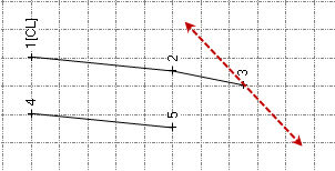
- In the First slope node drop-down list, select the node for which you want to define the first slope for the slope intersection.
The line segment for the new node will connect to this node.
Tip: You can also pick the slope node in the graphic pane of the template editor. To make the locations of nodes more obvious, select Options > Show node labels at the bottom of the editor.
- Click the First slope button, and select the appropriate cut slope type:
- Slope percent
 - Enter the percentage of slope from the Side slope from node (or the outer edge of a ditch if one is specified; see step 7) to the new node. Include a minus sign to indicate a negative slope. Or, select the slope in the Plan View (select two points) or template view.
 - Slope ratio
 - Enter the ratio of the slope from the Side slope from node (or the outer edge of a ditch if one is specified; see step 7) to the new node. Or, select the slope ratio in the Plan View (select two points) or template view.
 - Node to node
 - Select the node combination in the drop-down lists that provides the slope you want to use to specify the slope from the Side slope from node (or the outer edge of a ditch if one is specified; see step 7) to the new node. Or, select the nodes in the template view.
 - Table
 - Click the More button to display the Edit Table dialog. Then specify the slope between the Side slope from node (or the outer edge of a ditch if one is specified; see step 7) and the new node at each station in the corridor from the current template to the next template (or the end of the corridor).
 You can type the station in the Station field, or you can select it in the Plan View. You can type the slope value in the Slope field (include a minus sign to indicate a negative slope), or you can select the slope in the Plan View (select two points) or template view.
- Shareable slope table
 - If you have created a shareable slope table for the corridors alignment, you can use this to define the slope at specific stations along the alignment. Select the shareable slope table from the list, or click a shareable slope table line in the Superelevation Diagram.
- Slope percent
- In the First slope box, enter the slope from the First slope node. If you have selected Table or Shared slope table as your slope type ensure the table is selected in this field.
A negative number indicates the slope will be downward from the node to an increasing offset from the centerline, and upward from the node to a decreasing offset.
A positive number indicates the slope will be upward from the node to an increasing offset from the centerline, and downward from the node to a decreasing offset.
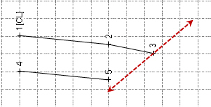
- In the Second slope node drop-down list, select the node for which you want to define the second slope for the slope intersection. Or, select the node in the template view.
- In the Second slope box, enter the slope from your Second slope node. If you have selected Table or Shared slope table as your slope type ensure the table is selected in this field.
The new node will be created at the intersection of the two slopes
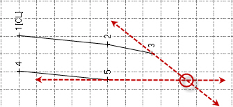
A line segment will be created to connect the new node with the node selected in the First slope node drop-down list. If you need to create a line segment to connect the new node with the node selected in the Second slope node drop-down list, use a Connect Nodes instruction.
- In the Name drop-down list, select the name you want to use for the new node. Or, type in a new template node name. Selecting or entering a template node name is optional. For additional information, see Create, Edit, and Delete Template Node Names.
- In the Material layers list, check boxes for the the material layers on which you want the line segment created by the instruction to appear.
Selecting a layer is optional. However, if you do not select a layer, no line segment is created. Corridor line segments are displayed in the Plan View and 3D View. If you export the corridor, they are used to create the exported corridor surface. For additional information on material layers, see Understanding Corridor Material Layers and Corridor Surfaces and Create, Edit, and Delete Material Layers.
- If you have any of the boxes for subgrades checked in the Material layers group, the Material above list is enabled. Select a pre-defined material as the material above the instruction that you are editing, or select <New> to open the Material and Site Improvement Manager where you can define materials. If shrinkage, bulkage, or compaction factors have been specified for an earthen material, they will be used in any corridor volume calculations.
Note: The use of material layers requires a license. See the Subscription Plans page. For a license matrix by command, see the License page in the TBC Community. Also see View and manage licensed features.
- Do one of the following:
- Click the Add After buttonto insert the new instruction after the selected instruction in the Instructions list.
- Click the Add Before buttonto insert the new instruction before the selected instruction in the Instructions list.
Note: If there are no instructions in the Instructions list, click either button to insert the new instruction as the first instruction in the list.
The new instruction is inserted into the Instruction list. The new line segment (if created) is displayed in the template view. The fields are cleared and you can repeat this procedure to create and add more instructions to the template.
Note: Once you have created corridor template instructions for one side of a corridor centerline, you can use the Mirror Instructions command button (located at the top of the Edit Corridor Template pane) to copy them to the other side of the centerline with reversed offsets. This can save you time and help you avoid errors when creating a corridor template. See Mirror Corridor Template Instructions for more information.
